A melt containment retention system

A melt and containment technology, which is applied in the field of melt containment retention systems, can solve the problems of inability to effectively resist the impact of melts and the inability to effectively deal with the overall falling of the lower head, so as to reduce the risk of radioactive leakage and achieve high latent heat absorption. Powerful, efficient cooling effect

Active Publication Date: 2020-01-31
NUCLEAR POWER INSTITUTE OF CHINA
View PDF9 Cites 6 Cited by
  • Summary
  • Abstract
  • Description
  • Claims
  • Application Information

AI Technical Summary

Problems solved by technology

[0007] However, the above two types have the following disadvantages: they cannot effectively resist the impact of the molten material, so they cannot effectively deal with the overall drop of the lower head

Method used


Image

  • A melt containment retention system
  • A melt containment retention system

Examples


Embodiment 1

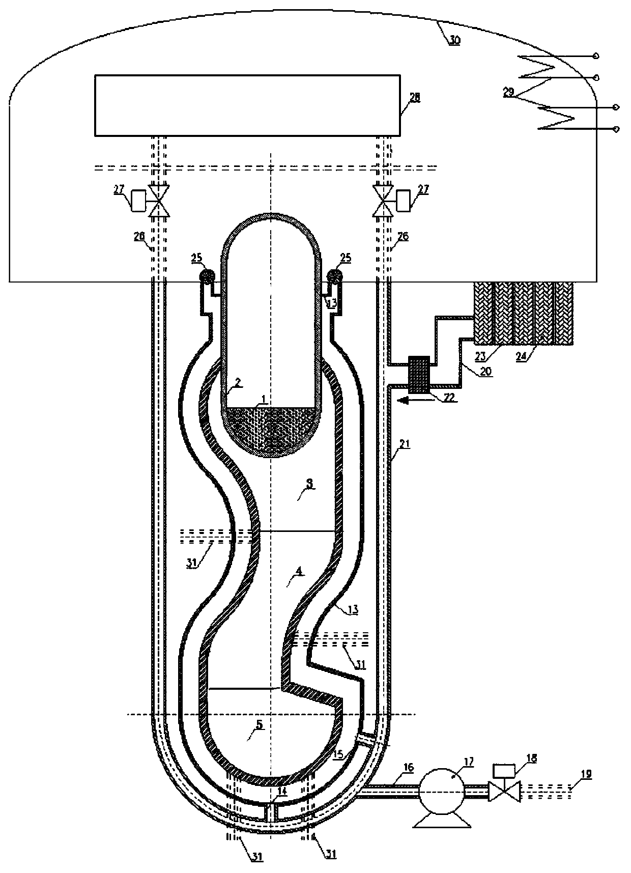
[0039] like figure 1 , 2 As shown, a melt containment retention system includes a retention part and a cooling system for cooling the retention part. The cooling system includes a connected cooling source device and a cooling water circuit. The cooling water circuit is connected to the retention part. The retention part includes a jacket The melt extension cavity is located outside the pressure vessel 2 and extends downward. The melt extension cavity is formed by surrounding the pressure vessel 2 with the first container 6 prepared by the cooling plate. The melt extension cavity flows along the flow direction of the melt 1 It has at least one first curved section buffer zone 3 for buffering the flow velocity of the molten material 1, at least one second curved section slow zone 4 for extending the flow channel and narrowing the flow channel, and a loading area at the bottom of the molten material extension chamber 5. The direction of curvature of both the buffer zone 3 of the...


PUM


Abstract

The invention discloses a molten matter containment retention system, which includes a retention part and a cooling system for cooling the retention part. The cooling system includes a connected cooling source device and a cooling water circuit. The cooling water circuit is connected to the retention part. The retention part includes The melt extension cavity is sleeved outside the pressure vessel and extends downward. The melt extension cavity is formed by surrounding the pressure vessel with the first container prepared by the cooling plate. The melt extension cavity has at least one The buffer zone of the first curved section for buffering the flow rate of the molten material, at least one slowing zone of the second curved section for extending the flow channel and narrowing the flow channel, and a loading area at the bottom of the molten material extension chamber, the first curved section buffers The direction of curvature of both the zone and the deceleration zone of the second bending section is oppositely set. It can effectively buffer the impact of high temperature melt.

Description

technical field [0001] The invention relates to the field of nuclear power accident mitigation, in particular to a containment containment system for molten matter. Background technique [0002] Since humans began to use nuclear energy, there have been many serious nuclear leakage accidents around the world, such as the Three Mile Island nuclear leakage accident in the United States, the Chernobyl nuclear leakage accident in the former Soviet Union, and the Fukushima nuclear leakage accident in Japan. By analyzing the development and treatment process of the above-mentioned nuclear leakage accidents, it can be found that keeping the radioactive core melt in the containment can ensure the integrity of the nuclear reactor safety barrier and greatly alleviate the further development and deterioration of severe nuclear reactor accidents. [0003] In order to keep the radioactive core melt in the containment more safely and reliably, a dual-barrier melt containment protection sys...

Claims


Application Information

Patent Timeline
Patent Type & Authority Patents(China)
IPC IPC(8): G21C9/016G21C15/18
CPCG21C9/016G21C15/18Y02E30/30
Inventor 张震李朋洲昝元锋卓文彬
Owner NUCLEAR POWER INSTITUTE OF CHINA
Why Eureka
Try Eureka