Reflective boundary, manufacturing method of reflective boundary, and antenna

A technology of reflecting boundaries and manufacturing methods, applied to antennas, electrical components, etc., can solve the problems of unfavorable antenna lightweight requirements, heavy products, and increased processing costs

Pending Publication Date: 2019-01-25
COMBA TELECOM TECH (GUANGZHOU) CO LTD
View PDF0 Cites 0 Cited by
  • Summary
  • Abstract
  • Description
  • Claims
  • Application Information

AI Technical Summary

Problems solved by technology

However, this technical solution has a limit between the thickness of the electromagnetic reflector and its size. The larger the size of the part, the correspondingly larger the wall thickness
In engineering practice, in order to obtain better part size and shape accuracy, the wall thickness of the basic electromagnetic reflector is often required to select a larger value, and the excessive wall thickness of the reflective boundary will lead to overweight products, which is not conducive to

Method used

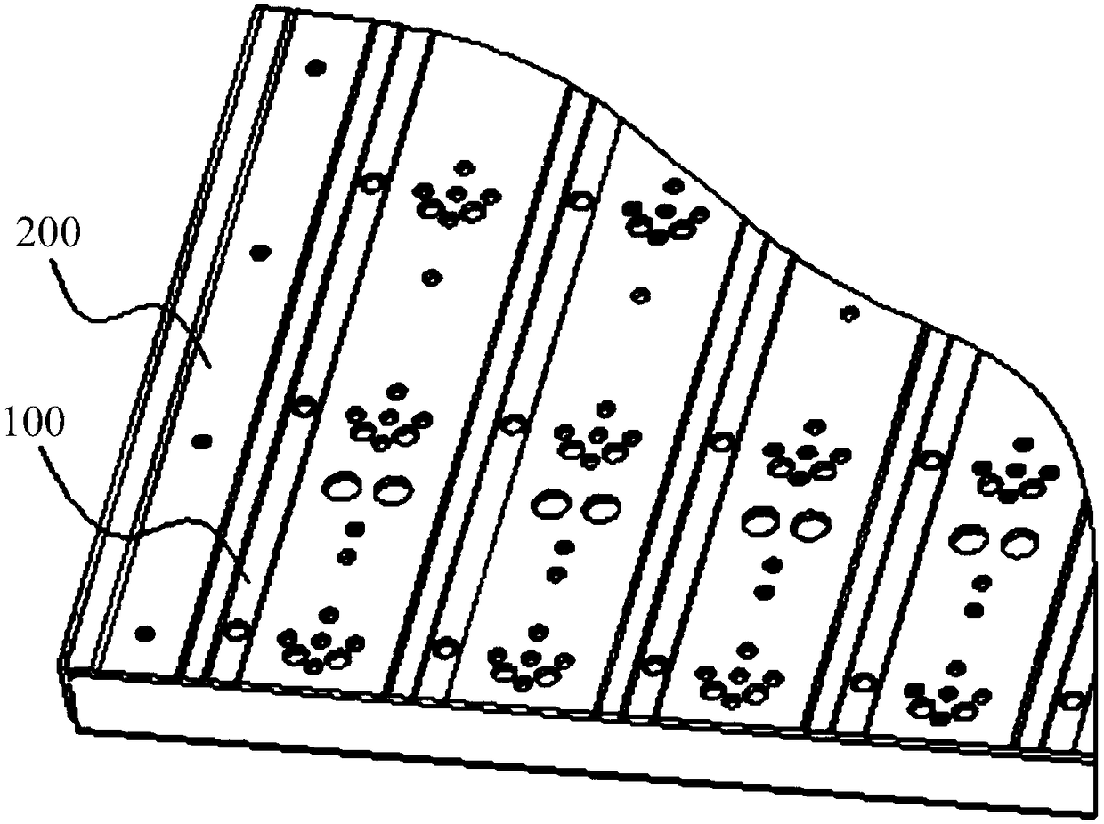
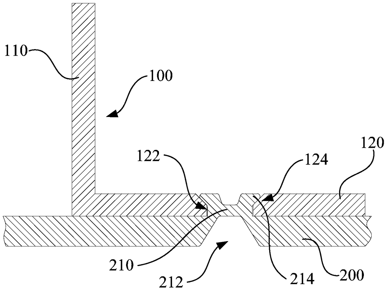
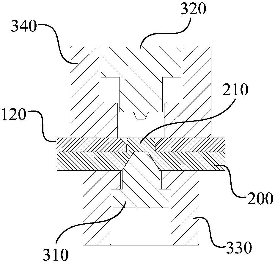

Image

  • Reflective boundary, manufacturing method of reflective boundary, and antenna
  • Reflective boundary, manufacturing method of reflective boundary, and antenna
  • Reflective boundary, manufacturing method of reflective boundary, and antenna

Examples


Embodiment Construction

[0039] In order to make the object, technical solution and advantages of the present invention clearer, the present invention will be further described in detail below in conjunction with the accompanying drawings and specific implementation methods. It should be understood that the specific embodiments described here are only used to explain the present invention, and do not limit the protection scope of the present invention.

[0040] It should be noted that when an element is referred to as being "fixed on", "disposed on", "fixed on" or "installed on" another element, it can be directly on the other element or there can also be an intervening element . When an element is referred to as being "connected to" another element, it can be directly connected to the other element or intervening elements may also be present. Furthermore, when one element is considered to be "fixed transmission connection" to another element, the two can be fixed in a detachable connection, or can b...


PUM

PropertyMeasurementUnit
Diameteraaaaaaaaaa

Abstract

A reflective boundary comprises a reflective plate and a spacer, The separator has a side plate and a connecting plate formed by bending relative to the side plate. The reflecting plate and the connecting plate are respectively formed with a convex part and a through hole, and the convex part can be fitted and inserted with the through hole. The convex part can be deformed in the through hole to rivet and consolidate the connecting plate and the reflecting plate together. The reflective boundary, on the one hand, the use of screws, On the other hand, the rivet connector is convenient to manufacture, and the thickness of the reflector plate need not be increased compared with the metal integrated forming scheme, which is conducive to the lightweight design of the rivet connector. The invention also discloses an antenna including the reflective boundary and a manufacturing method of the reflective boundary.

Description

technical field [0001] The invention relates to the technical field of antennas, in particular to a reflection boundary, a method for making the reflection boundary and an antenna. Background technique [0002] In mobile communication network coverage, the antenna is the basic device for sending and receiving signals, and the reflection boundary is the most basic and important unit in the antenna. The reflection boundary not only determines the realization of antenna circuit performance and radiation performance, but also plays a decisive role in structural strength and product weight. [0003] Reflective boundaries typically include reflective panels and spacers. At present, the technical solution generally adopted in the prior art is a technical solution in which the spacer and the reflection plate are formed separately and fixed by separate mechanical connectors (such as screws and rivets). In this technical solution, if screws are used as the connecting parts, on the o...

Claims


Application Information

Patent Timeline
IPC IPC(8): H01Q15/14H01Q19/10B21J15/14B21J15/38
CPCH01Q15/14H01Q15/141H01Q19/104B21J15/14B21J15/38
Inventor 余国鑫郑桂鑫段红彬岑宣良张齐
Owner COMBA TELECOM TECH (GUANGZHOU) CO LTD
Why Eureka
Try Eureka