
Reactive power optimization control method based on active power output of photovoltaic power station

A photovoltaic power station and optimization control technology, applied in photovoltaic power generation, electrical components, circuit devices, etc., can solve the problems of voltage fluctuation at the grid connection point, not taking into account the fluctuation of active power output, jeopardizing the safe and stable operation of the power system, and improving the economy. , reduce active power loss, improve the effect of internal voltage distribution

Pending Publication Date: 2019-01-25
NORTH CHINA ELECTRIC POWER UNIV (BAODING) +3
View PDF6 Cites 6 Cited by
  • Summary
  • Abstract
  • Description
  • Claims
  • Application Information

AI Technical Summary

Problems solved by technology

[0002] The randomness and fluctuation of light energy cause the active output of photovoltaic power plants to be unstable, which in turn causes voltage fluctuations at grid-connected points, seriously endangering the safe and stable operation of the power system. Therefore, large-scale photovoltaic power plants must have reactive voltage control capabilities
[0003] The traditional reactive power control of photovoltaic power plants takes the minimum voltage deviation of the grid-connected point as the control goal, does not consider the voltage deviation in the station and the economic problems of photovoltaic power plant operation, and does not take into account the fluctuation of active power output with the change of light intensity

Method used


Image

  • Reactive power optimization control method based on active power output of photovoltaic power station
  • Reactive power optimization control method based on active power output of photovoltaic power station
  • Reactive power optimization control method based on active power output of photovoltaic power station

Examples


Embodiment

[0093] Example program parameter description:

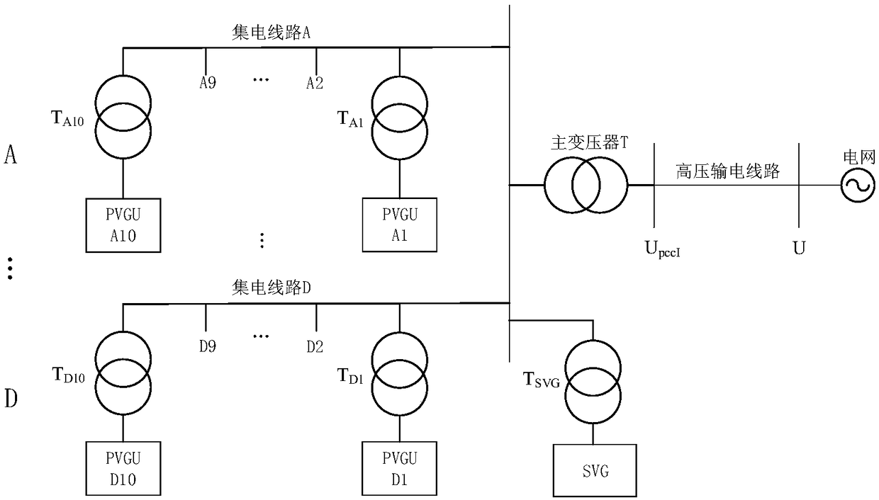
[0094] Such as figure 2 As shown, in this embodiment, the total installed capacity of the photovoltaic power station is 40MW, and there are 4 collector lines in total, and 10 groups of PVGUs with a distance of 1.2km and a capacity of 1MW are connected in parallel on each collector line, and are imported into the grid through a 0.29 / 10kV step-up transformer. Collector line; SVG capacity is -4~6MVar; boosted by 121 / 10.5kV main transformer, connected to grid through 40km transmission line.

[0095] In order to more clearly show the control effect of the reactive power optimization control scheme proposed in this paper, the following two different reactive power control methods are used for comparison.

[0096] Option 1: The photovoltaic inverter operates at unit power factor, and only SVG participates in reactive power compensation;

[0097] Scheme 2: Both the photovoltaic inverter and the SVG participate in reactive power compen...


PUM


Abstract

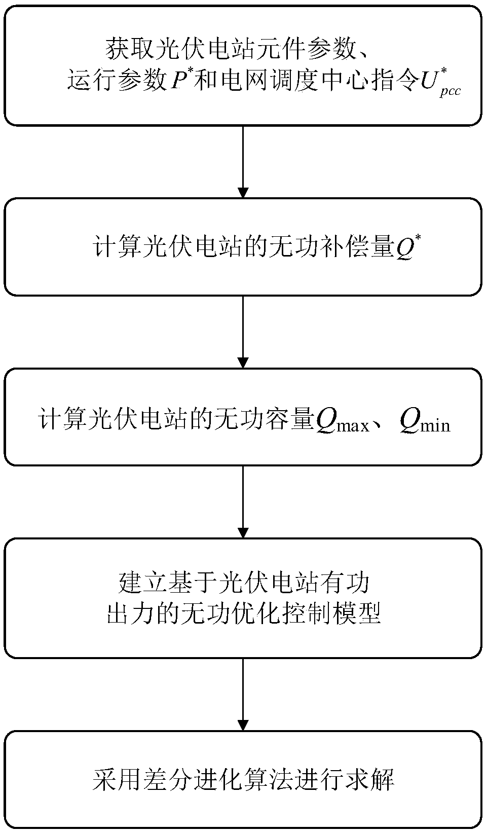
The invention discloses a reactive power optimization control method based on active power output of a photovoltaic power station, belonging to the technical field of photovoltaic power station operation control. The method of the invention comprises: the parameters of each photovoltaic inverter and SVG in the photovoltaic power station are obtained, The active power output P* of the photovoltaicpower station and the voltage control instruction of the grid connection point issued by the grid dispatching center (img file = 'DDA000179000293000011. TIF' wi= '126' he= '86' / ) are calculated to obtain the reactive power compensation amount of the photovoltaic power station Q*; Calculate the reactive power capacity Qmax, Qmin of the photovoltaic power station; Taking the reactive power output ofPVGU and SVG as the control object, taking the minimum voltage deviation and the minimum active power loss of photovoltaic power station as the optimization objective, and transforming the fuzzy theory into a single objective optimization problem, the reactive power optimization control model based on the active power output of photovoltaic power station is established. Differential evolutionaryalgorithm is used to solve the model.

Description

technical field [0001] The invention belongs to the technical field of operation control of photovoltaic power plants, and in particular relates to a reactive power optimization control method based on the active output of photovoltaic power plants. Background technique [0002] The randomness and fluctuation of light energy make the active output of photovoltaic power plants unstable, which in turn causes voltage fluctuations at the grid-connected point, which seriously endangers the safe and stable operation of the power system. Therefore, large-scale photovoltaic power plants must have reactive voltage control capabilities. [0003] The traditional reactive power control of photovoltaic power plants takes the minimum voltage deviation of the grid-connected point as the control goal, without considering the voltage deviation in the station and the economic problems of photovoltaic power plant operation, and does not take into account the fluctuation of active power output w...

Claims


Application Information

Patent Timeline
IPC IPC(8): H02J3/50H02J3/38
CPCH02J3/383H02J3/50H02J2203/20Y02E10/56
Inventor 聂雅楠刘文颖汪宁渤夏鹏周强王贤陈钊张雨薇王方雨丁坤朱丹丹马明张尧翔赵龙郭虎姚春晓王明松吕良张健美荣俊杰王定美曾文伟李宛齐冉忠胡阳朱丽萍李潇
Owner NORTH CHINA ELECTRIC POWER UNIV (BAODING)
Learn More