Wear-resisting cutter for balers

A baler and tool technology, applied in the field of metal cutting processing, can solve the problems of reducing tool life, accuracy impact, poor shock absorption effect, etc., and achieve the effect of eliminating energy generated by vibration, improving accuracy, and reducing vibration.

Pending Publication Date: 2019-01-29
南京申发冶金机械制造有限公司
View PDF4 Cites 0 Cited by
  • Summary
  • Abstract
  • Description
  • Claims
  • Application Information

AI Technical Summary

Problems solved by technology

Contemporary balers are mostly simple in structure, single in design, and limited in function. The current balers simply bundle the residue after receiving the goods. Some crops have roots still in the soil, and some have roots The leaves are exposed, and the field cannot be completely cleaned only by shoveling the board, causing the baler to not completely clean up the residue, which makes the effect of getting twice the result with half the effort
[0003] In some high-speed processing tools, the tool usually drives the clamping part with the high-speed operation of the machine, resulting in strong vibration, and the cutting part of the tool will also have a certain degree of stability on the clamping stability of the tool due to the force of the vibration. Influence, at present, the shock absorption effect of the tools on the market is poor, which reduces the dimensional accuracy and accuracy rate. In addition, the cutting edge of the tool that has been affected by the vibration for a long time will also be affected by more or less accuracy, thereby reducing the life of the tool. Therefore, it is necessary to A baler can only be realized with a wear-resistant cutter

Method used


Image

  • Wear-resisting cutter for balers
  • Wear-resisting cutter for balers
  • Wear-resisting cutter for balers

Examples


Embodiment Construction

[0019] The following will clearly and completely describe the technical solutions in the embodiments of the present invention with reference to the accompanying drawings in the embodiments of the present invention. Obviously, the described embodiments are only some, not all, embodiments of the present invention. Based on the embodiments of the present invention, all other embodiments obtained by persons of ordinary skill in the art without making creative efforts belong to the protection scope of the present invention.

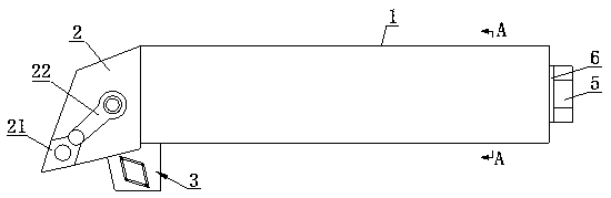
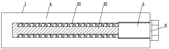
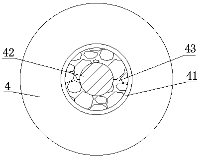
[0020] see Figure 1-4 , a wear-resistant cutter for a baler, comprising a cutter body 1, the left end of the cutter body 1 is provided with a cutter head 2, and the cutter head 2 is fixedly connected with the cutter body 1; the left end of the cutter head 2 is provided with a wear-resistant blade 21, the cutter The right end of the head 2 is provided with a fixing device 22, and the wear-resistant blade 21 and the fixing device 22 are fixedly connected with t...


PUM


Abstract

The invention discloses a wear-resisting cutter for balers. The wear-resisting cutter comprises a cutter body, a cutter head is arranged at the left end of the cutter body, and the cutter head is fixedly connected with the cutter body. The left end of the cutter head is provided with a wear-resisting blade; a shock absorbing plate is arranged in the center of the through hole, and shock absorbingsprings are arranged on four corners of the shock absorbing plate, and the shock absorbing plate is connected with a spring fixing seat through the shock absorbing springs; the right end of the cutterbody is provided with a cutter handle, the center of the cutter handle is provided with a mounting hole, the center of the mounting hole is provided with a reinforcing body, and the outer side of thereinforcing body is provided with shock absorbing particles. When the wear-resistant cutter for this baler is in use, the shock absorbing plate is inclined to the left by 30-45 degrees, the shock absorbing springs are arranged on the four corners of the shock absorbing plate, the shock absorbing plate is connected with the spring fixing seat through the shock absorbing springs, and the energy consumption of the tool vibration can be reduced through the mechanical vibration of the shock absorbing plate in the use process, thereby reducing the tool vibration; the whole damping effect is good, the tool wear resistance is higher, and the tool damage frequency is reduced.

Description

technical field [0001] The invention relates to the technical field of metal cutting, in particular to a wear-resistant cutter for a baler. Background technique [0002] The baler is mostly used to bundle the roots or weeds of the crops in the field after the crops are received. The baler is mostly divided into a square baler and a round baler. The wide use of the baler makes the The cleaning of the farmland is guaranteed, therefore, the baler has become a necessary machine for post-harvest cleaning in contemporary agriculture. Contemporary balers are mostly simple in structure, single in design, and limited in function. The current balers simply bundle the residue after receiving the goods. Some crops have roots still in the soil, and some have roots If the leaves are exposed, the field cannot be completely cleaned only by shoveling the board, resulting in the baler not being able to completely clean up the residue, thus making the effect of getting twice the result with h...

Claims


Application Information

Patent Timeline
Patent Type & Authority Applications(China)
IPC IPC(8): A01F15/08
CPCA01F15/08
Inventor 周克泉张健武玉梅周明月
Owner 南京申发冶金机械制造有限公司
Why Eureka
Try Eureka