
An intelligent remote electronic monitoring device

An electronic monitoring and remote technology, applied in closed-circuit television systems, chemical instruments and methods, cleaning methods using liquids, etc., can solve problems affecting monitoring clarity, inconvenient installation location, dust accumulation, etc., to improve replacement and maintenance efficiency , Avoid image acquisition blur, reduce the effect of dust accumulation

Active Publication Date: 2020-06-30
菏泽众达信息科技服务有限公司
View PDF7 Cites 0 Cited by
  • Summary
  • Abstract
  • Description
  • Claims
  • Application Information

AI Technical Summary

Problems solved by technology

[0003] At present, the commonly used surveillance cameras have complex installation structures, are not easy to install and disassemble, and are not conducive to the replacement and maintenance of surveillance cameras. Tools are required for installation and disassembly, which is not conducive to the promotion and use of surveillance cameras; general surveillance cameras have certain limitations in use. The same area can be monitored, and the monitoring area of ​​the camera cannot be changed; the lens of the surveillance camera is generally in direct contact with the environment, and the environment contains a lot of dust, which adheres to the surface of the lens and blocks the lens, resulting in blurred or even unrecognizable images image, affecting the normal monitoring work of the surveillance camera
[0004] The current camera needs manual wiping when wiping, which is very inconvenient due to the installation position of the camera. Although there are some self-wiping cameras, the current wiping generally only depends on the back and forth movement or rotation of the wiping seat. , this kind of wiping can easily cause more dust to accumulate on the lens, causing the lens to become blurred and affecting the clarity of monitoring

Method used


Image

  • An intelligent remote electronic monitoring device
  • An intelligent remote electronic monitoring device
  • An intelligent remote electronic monitoring device

Examples


Embodiment Construction

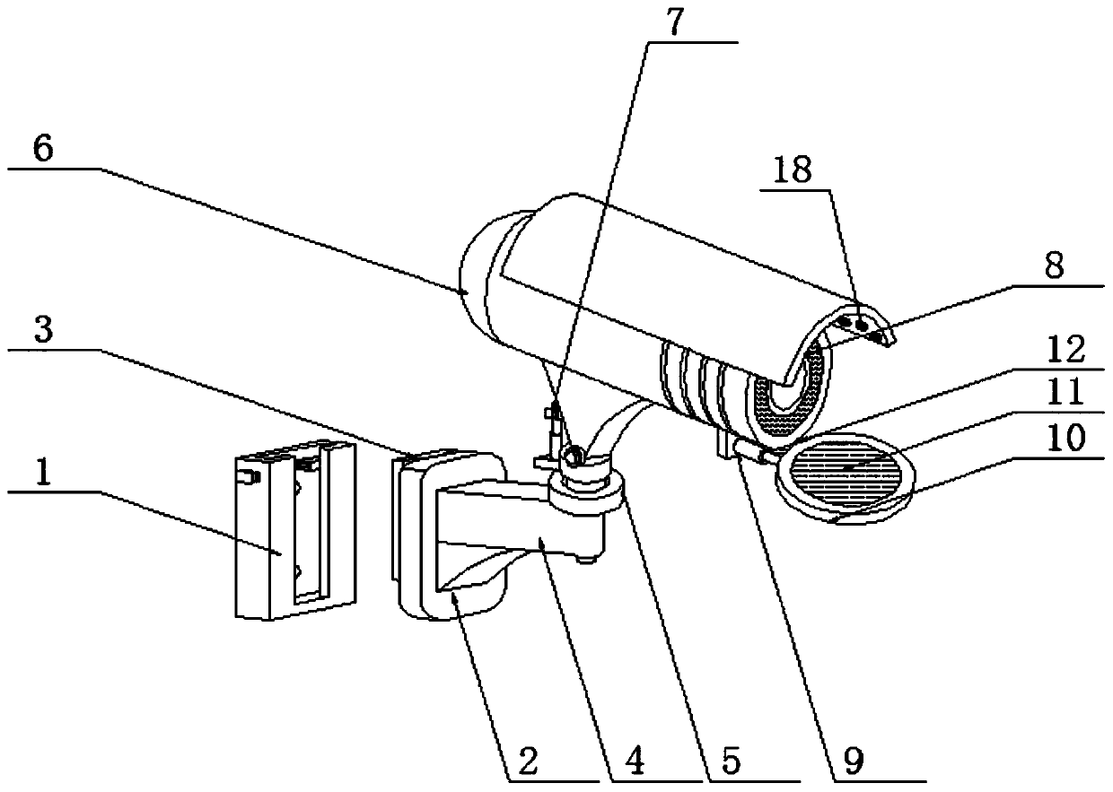
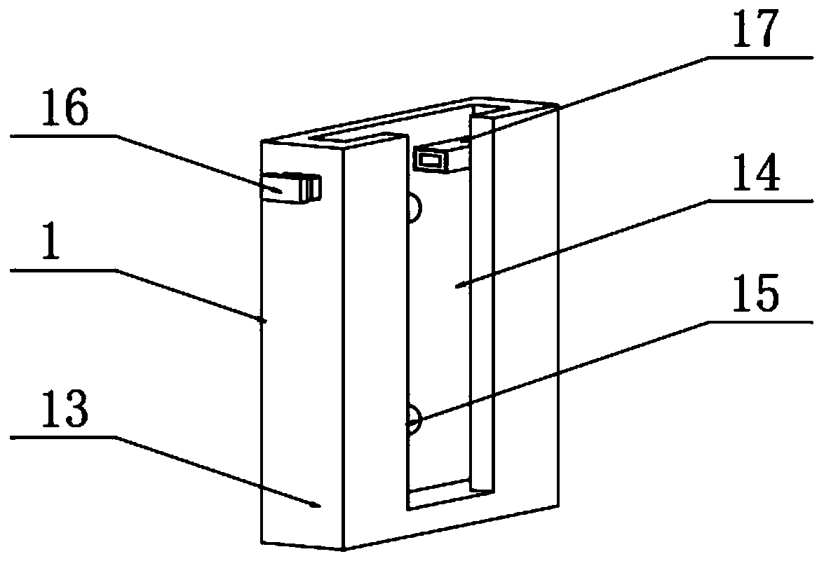
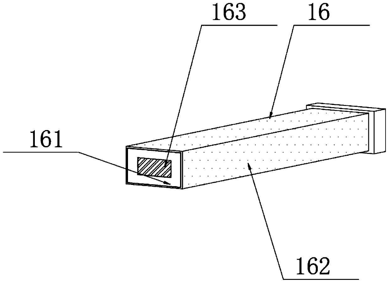
[0032] see Figure 1-7 , in an embodiment of the present invention, an intelligent remote electronic monitoring device includes a mounting assembly, an angle adjustment assembly, a monitoring camera body 6, an upper cover, a dust blowing assembly, and a wiping assembly. The monitoring device is detachably installed at the position to be installed; the installation assembly is provided with an angle adjustment assembly, and the output end of the angle adjustment assembly is connected with the monitoring camera body 6; the monitoring camera body 6 is provided with a The upper casing fixed thereon is characterized in that the front end of the upper casing stretches out from the lens end of the monitoring camera body 6; Dust assembly, the dust blowing nozzle of the dust blowing assembly is arranged towards the lens of the monitoring camera body 6, and the lower end of the monitoring camera body 6 is connected with a rotatable setting so that it can be fastened to the monitoring ca...


PUM


Abstract

The invention discloses an intelligent remote electronic monitoring device, which includes an installation component, an angle adjustment component, a monitoring camera body, an upper cover, a dust blowing component and a wiping component. The lower end of the monitoring camera body is connected with a rotatable setting so that it can be buckled The wiping assembly is installed on the lens of the surveillance camera body. When cleaning, the dust blowing assembly first blows air on the lens to remove dust for a period of time, and then the wiping assembly rotates and engages with the lens of the surveillance camera body for wiping; the wiping assembly is provided with The invention has a wiping liquid injection assembly that automatically sprays wiping liquid and a suction assembly that sucks up the wiping liquid. The invention facilitates the installation and fixation of the monitoring camera body. The installation structure is simple and is beneficial to the replacement and maintenance of the monitoring camera body. It is not required during installation and disassembly. With the help of tools, the convenience of installation and disassembly of the surveillance camera body can be improved, and the replacement and maintenance efficiency of the surveillance camera body can be improved, which is conducive to the promotion and use of the surveillance camera body.

Description

technical field [0001] The invention relates to the technical field of electronic monitoring equipment, in particular to an intelligent remote electronic monitoring device. Background technique [0002] The camera generally has basic functions such as video recording, broadcasting, and static image capture. After collecting images through the lens, the photosensitive component circuit and control components in the camera process the image and convert it into a digital signal that can be recognized by the computer. A typical application is intelligent remote video surveillance. [0003] At present, the commonly used surveillance cameras have complex installation structures, are not easy to install and disassemble, and are not conducive to the replacement and maintenance of surveillance cameras. Tools are required for installation and disassembly, which is not conducive to the promotion and use of surveillance cameras; general surveillance cameras have certain limitations in u...

Claims


Application Information

Patent Timeline
Patent Type & Authority Patents(China)
IPC IPC(8): B08B5/02B08B1/04B08B3/08H04N7/18
CPCH04N7/18B08B3/08B08B5/02B08B1/32
Inventor 沈张果
Owner 菏泽众达信息科技服务有限公司
Learn More