Bow thruster coupler shrinkage fit tool

A coupling and red sleeve technology is applied in the field of bow thrust coupling red sleeve tooling, which can solve the problem of inability to operate with bare hands.

Active Publication Date: 2019-01-29
CHENGXI SHIPYARD
View PDF6 Cites 0 Cited by
  • Summary
  • Abstract
  • Description
  • Claims
  • Application Information

AI Technical Summary

Problems solved by technology

However, during the installation process of the red sleeve, since the temperature of the coupling red sleeve reaches 130°C, it is impossible to operate...

Method used


Image

  • Bow thruster coupler shrinkage fit tool
  • Bow thruster coupler shrinkage fit tool
  • Bow thruster coupler shrinkage fit tool

Examples


Embodiment 1

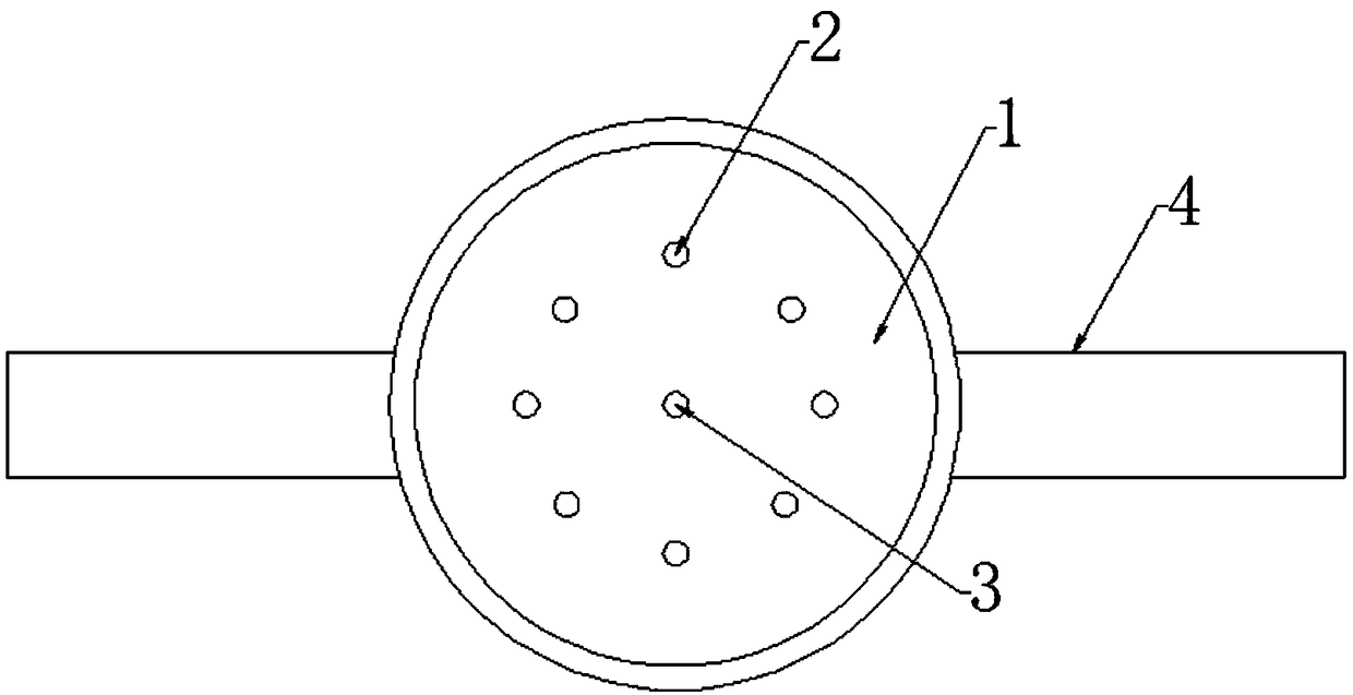
[0020] like figure 1 As shown, the present invention is a bow thruster coupling red sleeve tooling, including a tray 1, a number of hollow cylinders 2 are evenly arranged in the center of the tray bottom plate, and the height of the cylinders is not greater than the height of the coupling. The radius of the circle surrounded by the cylinder is greater than the radius of the coupling, and a heating component is arranged in the cylinder; a through hole 3 is arranged at the center of the tray, a cylindrical protrusion is arranged on the through hole, and an internal thread is arranged on the inner wall of the cylindrical protrusion; A handle 4 is provided on the outer periphery of the tray.

[0021] The method of fitting the coupling vertically to the motor shaft is as follows: firstly heat and expand the coupling to the required size at the heating source, then place the heated and expanded coupling on the tooling pallet by hoisting or clamping In the circular accommodation cav...

Embodiment 2

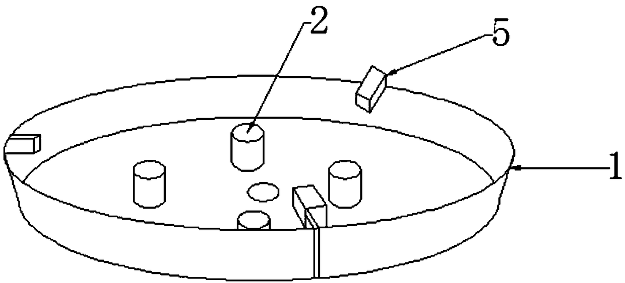
[0023] like figure 2 As shown, a bow thruster coupling red sleeve tooling includes a tray 1, and a number of hollow cylinders 2 are uniformly arranged in the center of the tray bottom plate. The height of the cylinders is not greater than the height of the coupling. The radius of the enclosed circle is greater than the radius of the coupling, and a heating component is provided in the cylinder; a cold air system is provided on the lower surface of the tray, and several air outlets 5 of the cold air system are evenly arranged on the outer edge of the tray, and all face the center of the tray .

Embodiment 3

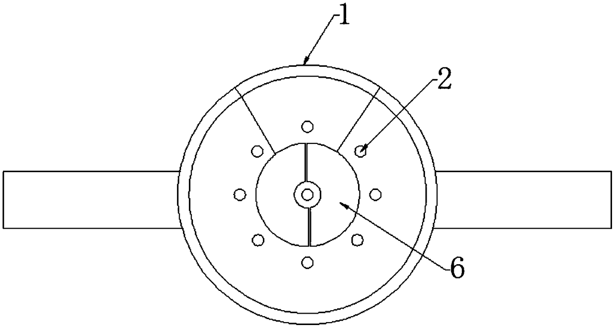
[0025] like image 3 , 4 As shown, a bow thruster coupling red sleeve tooling includes a tray 1, and a number of hollow cylinders 2 are uniformly arranged in the center of the tray bottom plate. The height of the cylinders is not greater than the height of the coupling. The radius of the enclosed circle is larger than the radius of the coupling, and a heating component is arranged in the cylinder; the circular bottom plate area surrounded by the cylindrical protrusion on the bottom plate of the tray and several hollow cylinders is provided with an arc-shaped sheet temperature sensor 6. The temperature sensor is sequentially connected with the digital display screen 7 and the power supply 8 on the bottom surface of the pallet; a level 9 is arranged on the bottom surface of the pallet.


PUM


Abstract

The invention discloses a bow thruster coupler shrinkage fit tool. The bow thruster coupler shrinkage fit tool comprises a tray. Multiple hollow column bodies are evenly arranged in the circumferential direction of the center of a bottom plate of the tray, the heights of the column bodies are not larger than the height of a coupler, the radius of a circle defined by the column bodies is larger than that of the coupler, and heating parts are arranged in the column bodies. The tool has the beneficial effects of being simple in structure, convenient to use, safe and reliable, the heating parts are arranged, the coupler is firstly heated and then moved to the tray of the tool, switches of the heating parts are switched on, the coupler continues to be heated or subjected to heat preservation, then the coupler aligns at a motor shaft to complete vertical shrinkage fit, heating and aligning are carried out simultaneously, sleeving is achieved through one step, and no faults are easily caused;through supporting of the bottom plate of the tray, the heated coupler is not likely to deform, the coupler is completely cooled after being subjected to in-place sleeving, it is avoided that the coupler is subjected to cold deflation and fixation before being in place, and material waste is avoided; and the space defined by the hollow column bodies is used for containing the heated coupler, andit is avoided that the coupler slides on the bottom plate of the tray back and forth, so that alignment of the coupler and the motor shaft is affected.

Description

technical field [0001] The invention relates to the technical field of tooling equipment for ships, in particular to a red sleeve tooling for a bow thruster coupling. Background technique [0002] In modern ships, the bow side thruster motor and the side thruster are connected through a coupling, and the coupling and the shaft are interference fit, which need to be installed with a red sleeve, that is, the outer diameter of the motor shaft and the coupling are processed according to the amount of interference. Then heat the coupling to make the inner hole expand. The inner diameter of the inner hole exceeds the outer diameter of the shaft by about 2mm. Quickly insert the coupling onto the outer circle of the motor shaft. It is fixed to the shaft for natural cooling, and the coupling is in place after the bolts are tightened. However, during the installation of the red sleeve, since the temperature of the coupling’s red sleeve reaches 130°C, it is impossible to operate with ...

Claims


Application Information

Patent Timeline
IPC IPC(8): B23P11/02
CPCB23P11/025
Inventor 田春雷
Owner CHENGXI SHIPYARD
Why Eureka
Try Eureka