Hand-eye calibration and coordinate conversion method

A technology of coordinate transformation and hand-eye calibration, which is applied to manipulators, program-controlled manipulators, manufacturing tools, etc., can solve the problems of increasing calibration errors, limited shooting range, and concentrated distribution of collected data samples, so as to reduce calibration errors and simplify hand-eye The effect of the calibration process

Inactive Publication Date: 2019-01-29
HEFEI UNIV OF TECH
View PDF4 Cites 16 Cited by
  • Summary
  • Abstract
  • Description
  • Claims
  • Application Information

AI Technical Summary

Problems solved by technology

Some scholars proposed to complete the calibration between systems by shooting calibration targets between calibration cameras, but the calibration process requires multiple cameras to work at the same time, and the calibration process is more complicated; some scholars proposed to complete the picking robot based on binocular vision through the least square method Hand-eye calibration, but the manual teaching is introduced into the calibration process, which increases the calibration error, and the error reaches more than 10mm. Secondly, the fixed binocular stereo vision has a limited shooting range due to the fixed structure of the camera, which is limited after the camera is installed. The movement space of the manipulator leads to the distribution of collected data samples is too concentrated, and too many linearly related invalid data may be obtained, resulting in an increase in calibration error

Method used


Image

  • Hand-eye calibration and coordinate conversion method
  • Hand-eye calibration and coordinate conversion method
  • Hand-eye calibration and coordinate conversion method

Examples


Embodiment Construction

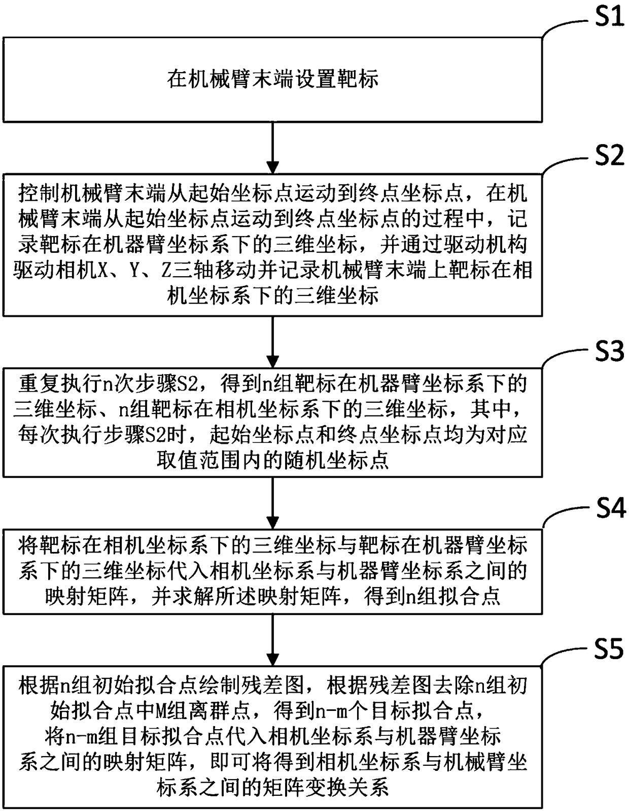
[0022] refer to figure 1 , a kind of hand-eye calibration and coordinate transformation method that the present invention proposes, comprises:

[0023] Step S1, setting a target at the end of the robotic arm, the robotic arm being a six-degree-of-freedom robotic arm.

[0024] In the specific scheme, the target is pasted on the end of the mechanical arm. The mechanical arm adopts a six-degree-of-freedom mechanical arm. Each degree of freedom of the mechanical arm is realized by the independent drive joints of its manipulator. The joints and degrees of freedom express mechanical The mobility aspects of the arms are synonymous. The six-degree-of-freedom robotic arm has six independently driven joint structures, which can realize any position and posture of the target in its workspace.

[0025] Step S2, control the movement of the end of the mechanical arm from the initial coordinate point to the end coordinate point, record the three-dimensional coordinates of the target in the...


PUM


Abstract

The invention discloses a hand-eye calibration and coordinate conversion method. The method comprises the steps that a target is arranged at the tail end of a mechanical arm; the tail end of the mechanical arm is controlled to move from the initial coordinate point to the terminal point coordinate point, in the process that the tail end of the mechanical arm moves from the initial coordinate pointto the end point coordinate point, the n-time targets of the three-dimensional coordinates in a camera coordinate system and the three-dimensional coordinates of a machine arm coordinate system are recorded, coordinates of the n groups of targets under the camera coordinate system and coordinates of the machine arm coordinate system are obtained, the coordinates of the target under the camera coordinate system and the dimensional coordinates of the machine arm coordinate system are substituted into a mapping matrix between the camera coordinate system and the machine arm coordinate system tosolve the mapping matrix, and n groups of fitting points are obtained; a residual graph is drawn according to the n groups of initial fitting points, the m groups of outlier points in the n groups ofinitial fitting points are removed, and the n-m groups of target fitting points are substituted into a mapping matrix between the camera coordinate system and the machine arm coordinate system, so that a matrix transformation relation between the camera coordinate system and the mechanical arm coordinate system can be obtained.

Description

technical field [0001] The invention relates to the technical field of hand-eye calibration, in particular to a hand-eye calibration and coordinate conversion method. Background technique [0002] In the fruit and vegetable picking robot control with visual feedback, the calibration of the hand-eye system (ie, the conversion between the camera coordinate system and the robot arm coordinate system) is very important, which directly affects the robot's operating accuracy. Binocular stereo vision is a method that uses more target recognition and positioning. Because the world coordinate system and the camera coordinate system are right-handed coordinate systems, they will not be deformed. We want to convert the coordinates in the world coordinate system to the coordinates in the camera coordinates. [0003] In recent years, many scholars have conducted a lot of research on the calibration method between the visual system and other coordinate systems. Some scholars proposed t...

Claims


Application Information

Patent Timeline
Patent Type & Authority Applications(China)
IPC IPC(8): B25J9/16
CPCB25J9/1692
Inventor 丁雷鸣严亚飞赵丹阳王庆苗东东徐海明吕品
Owner HEFEI UNIV OF TECH
Why Eureka
Try Eureka