
Bulge detection device and detection method in an automatic wiring control system

A detection device and automatic wiring technology, which is applied in transportation and packaging, thin material handling, and delivery of filamentous materials, etc. It can solve problems such as large manpower consumption, cable bulging, and untimely after-sales feedback, so as to reduce labor intensity. , Guarantee quality and save human resources

Active Publication Date: 2021-12-10
苏州凌犀物联网技术有限公司
View PDF12 Cites 0 Cited by
  • Summary
  • Abstract
  • Description
  • Claims
  • Application Information

AI Technical Summary

Problems solved by technology

However, in the cable manufacturing process, due to the need for sealing, heating, water cooling and other processes, a certain section of the cable may have a bulge. At present, the main method used for bulge detection is manual inspection during the cable production process. , which requires a lot of manpower; the second is to determine whether the cable has a bulge through after-sales feedback after the cable leaves the factory, but because the after-sales feedback is not timely, it is impossible to improve the process in time and improve the quality of the cable production

Method used


Image

  • Bulge detection device and detection method in an automatic wiring control system
  • Bulge detection device and detection method in an automatic wiring control system
  • Bulge detection device and detection method in an automatic wiring control system

Examples


Embodiment 1

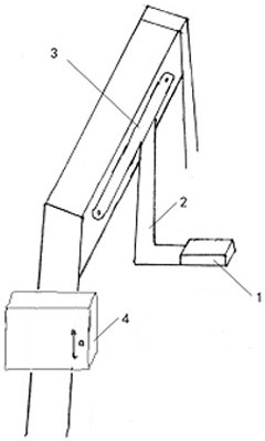
[0033] like figure 1 As shown, according to an embodiment of the present invention, the control system for automatic cable arrangement provided by the present invention includes an automatic cable arrangement head (1), a longitudinal axis (2), a transverse axis (3), and a control box (4) and stand. The transverse axis (3) is fixedly installed on the beam of the bracket, the upper end of the longitudinal axis (2) is suspended and installed on the transverse axis (3), and a mechanical arm is connected to the lower end, and the mechanical arm is at right angles to the longitudinal axis (2) , the front end of the mechanical arm is equipped with an automatic wire-laying machine head (1).

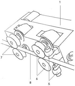
[0034] like figure 2 , Figure 4 and Figure 7 As shown, the automatic cable arrangement head (1) includes the head body, the reversing detection device (5) installed on the body, the cable clamping device (6), the bulge detection device (7), and the initial positioning device of the head (...

Embodiment 2

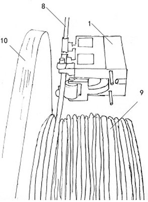
[0045] like Figure 4 , according to another embodiment of the present invention, the front end of the automatic cable arrangement head (1) is also equipped with a head initial positioning device (11) and a front end cable limiting device (12).

[0046] The initial positioning device (11) includes a laser locator. During the automatic cable arrangement process, the laser locator always emits a red laser. During the rotation and coiling of the cable pulley, the red laser emitted by the laser locator always shines on the at the highest point. Before the automatic wiring control system starts to operate, the automatic wiring head (1) needs to be initially positioned at a suitable position. At this time, the automatic wiring head (1) is controlled from top to bottom driven by the longitudinal axis (2) Move, when the automatic cable arrangement head (1) moves down until the red laser emitted by its laser positioner hits the highest point of the cable pulley shaft, the automatic ca...

Embodiment 3

[0051] like figure 2 , according to another embodiment of the present invention, a bulge detection device (7) is installed on the body of the automatic wire arranging machine head (1), which can realize real-time monitoring of cable parameters. , it can quickly and accurately locate the bulge in the cable to ensure the quality of the cable when it leaves the factory.

[0052] Image 6 It is the front view of the local structure of the automatic wire-laying machine head of the present invention (the figure obtained by rotating the front view by 90 degrees), in Image 6 Among them, the bulge detection device (7) is composed of two parts with the same shape, and the cable (8) passes through the middle of the two parts of the bulge detection device (7), and the two parts are symmetrical up and down with respect to the cable (8) Install. In a preferred embodiment, the front end of each part of the bulge detection device (7) is provided with a transmission wheel that can rotate ...


PUM


Abstract

The invention relates to a bulge detection device and a detection method in an automatic cable arrangement control system, which are suitable for the field of cable manufacturing. The invention provides a bulge detection device (7) in an automatic cable arrangement control system, the system includes an automatic cable arrangement head (1), a longitudinal axis (2), a transverse axis (3), and a control box (4) and a bracket; the bulge detection device (7) is installed on the body of the automatic wire-laying machine head (1); the bulge detection device (7) includes two parts with the same shape, and at the front end of each part A transmission wheel that can rotate around the shaft is provided, and the bottoms of the two parts are meshed through gear teeth, and are respectively fixed with the body of the automatic cable arrangement head (1) through the connecting piece, and can rotate around the connecting piece; the cable (8 ) passes between the two transmission wheels on the two parts of the bulge detection device (7), and the two transmission wheels are symmetrically installed up and down with respect to the cable (8).

Description

technical field [0001] The invention belongs to the technical field of cable manufacturing, and in particular relates to a bulge detection device and a detection method in an automatic cable arrangement control system. Background technique [0002] In the cable manufacturing industry, long cables need to be neatly wound on the cable pulley layer by layer. At present, wiring can be realized in two ways, manual or automatic. However, in the cable manufacturing process, due to the need for sealing, heating, water cooling and other processes, a certain section of the cable may have a bulge. At present, the main method used for bulge detection is manual inspection during the cable production process. , This requires a lot of manpower; the second is to determine whether the cable has a bulge through after-sales feedback after the cable leaves the factory, but because the after-sales feedback is not timely, it is impossible to improve the process in time and improve the quality of...

Claims


Application Information

Patent Timeline
Patent Type & Authority Patents(China)
IPC IPC(8): B65H54/28B65H63/00
CPCB65H54/286B65H63/006B65H2701/34
Inventor 万能刘斐斓刘诗华肖彬
Owner 苏州凌犀物联网技术有限公司
Learn More