
Motor linear array synchronous bidirectional hybrid centrifugal damping wind power generation device

A technology of wind power generation device and linear array, which is applied to wind turbines, wind turbines, and combinations of wind turbines at right angles to the wind direction, can solve the problems of unstable power generation, waste of energy consumption, abandoned wind, etc., and achieve stable power generation voltage, Easy to observe and good stability

Pending Publication Date: 2019-01-29
刘春梅
View PDF7 Cites 0 Cited by
  • Summary
  • Abstract
  • Description
  • Claims
  • Application Information

AI Technical Summary

Problems solved by technology

[0002] Among the existing renewable new energy power generation and utilization devices, solar energy and wind energy are the most converted power generation devices. Among them, the utilization of wind energy has been developed for many years. The utilization of wind energy relies on the conversion of wind energy into mechanical energy for power generation, but the existing technology The wind power generation device in the wind power generation device has low power generation efficiency, needs to start and cut into the wind speed higher than 7 m / s, low wind energy utilization rate, high mechanical speed of the generator system, waste of energy consumption due to the need for wind direction tracking devices, and a mechanical failure will bring the system outage , high failure rate
The equipment is huge, the tip speed ratio is high, the noise is high, and the endless death caused by the inhalation of birds is very unfavorable to the ecological environment. Because the wind speed affects the generator speed or high or low power generation is very unstable, it can be called garbage power, which cannot meet the needs of wind resources in different regions. , severe wind abandonment, and many other technical problems

Method used


Image

  • Motor linear array synchronous bidirectional hybrid centrifugal damping wind power generation device
  • Motor linear array synchronous bidirectional hybrid centrifugal damping wind power generation device
  • Motor linear array synchronous bidirectional hybrid centrifugal damping wind power generation device

Examples


Embodiment 1

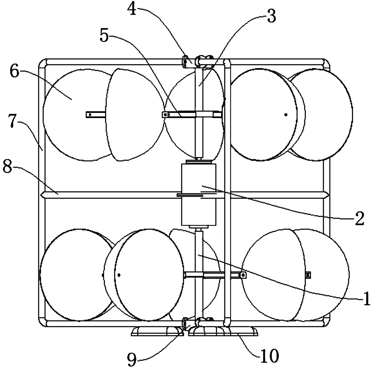
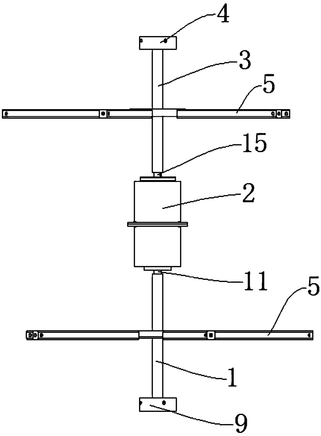
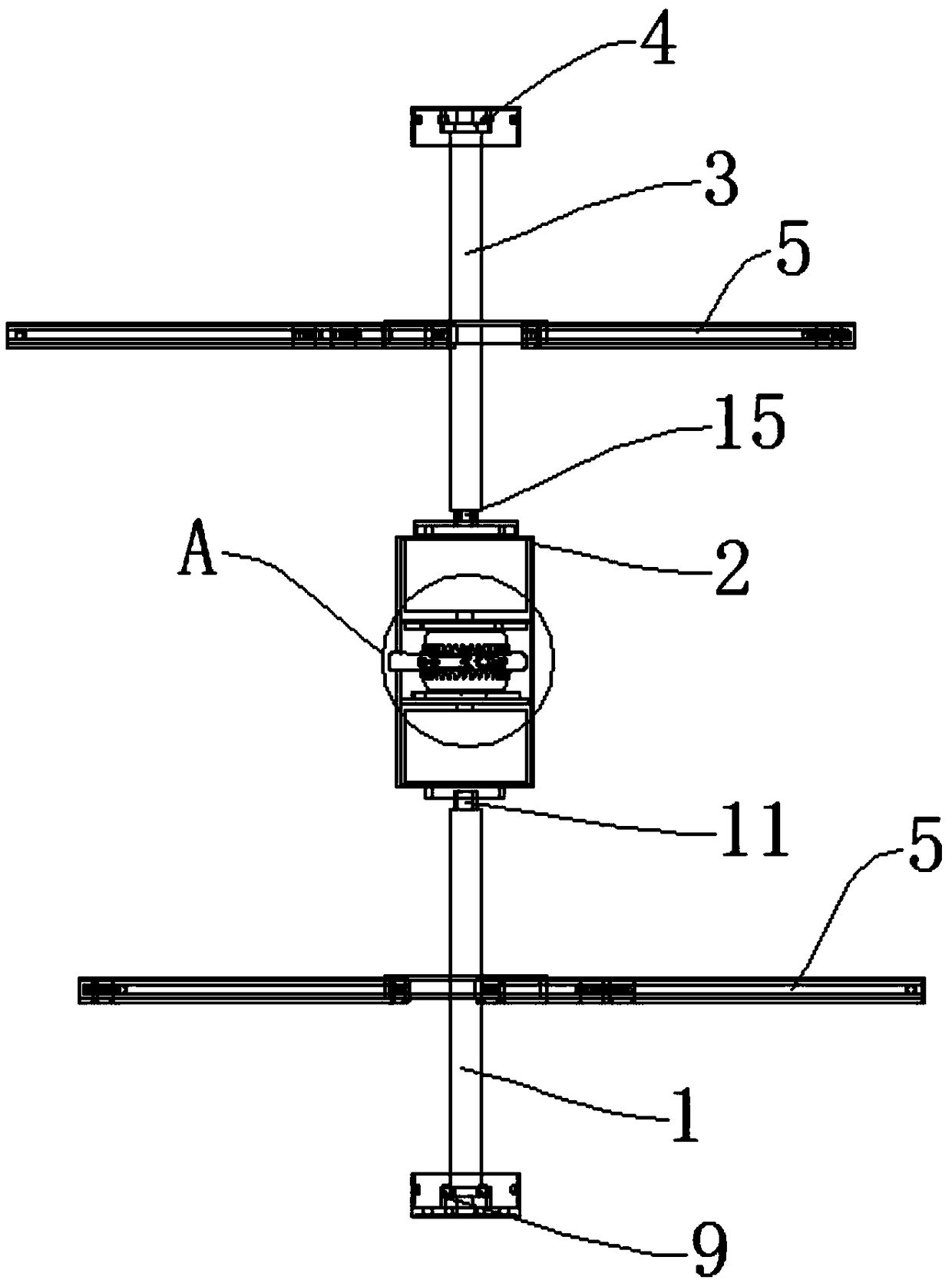
[0032] like Figure 1-Figure 4 As shown, the motor linear array synchronous two-way compound dynamic centrifugal damping wind power generation device includes a vertically arranged power generation group 2. The upper and lower sides of the power generation group 2 are coaxially provided with an upper transmission shaft 3 and a lower transmission shaft 1. The upper transmission shaft 3 The upper end is rotatably arranged in the upper bearing seat 4, and the lower end of the lower transmission shaft 1 is rotatably arranged in the lower bearing seat 9. The upper bearing seat 4 and the lower bearing seat 9 are fixedly connected by four supporting frames 7, and between the supporting frame 7 and the generator set 2 Through the fixed connection of the connecting rod 8, the setting of the connecting rod 8 can improve the stability of the coaxial fixed housing 17 of the motor, and at the same time facilitate the line connection between the upper generator 16 and the lower generator 20,...

Embodiment 2

[0042] like Figure 5 As shown, Embodiment 2 is an improvement on the basis of Embodiment 1. The upper centrifugal damping body 14 includes a centrifugal damping disc 21, which is fixedly connected to the upper rotating shaft 15. The centrifugal damping disc 21 is rotatably connected with a number of centrifugal dampers. The hoof 24, the rotating shaft of the centrifugal damping hoof 24 is eccentrically arranged with the centrifugal damping disc 21, and the side of the centrifugal damping body facing the center of the centrifugal damping disc 21 is fixedly connected with a tension spring 22, and the other end of the tension spring 22 is connected near the center of the centrifugal damping disc 21 The structure of the lower centrifugal damping body 19 is the same as that of the upper centrifugal damping body 14 , and the centrifugal damping disc 21 of the lower centrifugal damping body 19 is fixedly connected with the lower rotating shaft 11 .

[0043] The upper centrifugal dam...

Embodiment 3

[0046] like figure 1 As shown, Embodiment 3 is improved on the basis of Embodiment 2, and a lamp box 10 is fixedly installed at the bottom of the support frame 7 .

[0047] The arrangement of the light box 10 enables the power generating device to have a lighting effect, and at the same time facilitates the observation of the working conditions of the power generating set 2 at night.

[0048] The remaining structures and working principles of Embodiment 3 are the same as those of Embodiment 2.


PUM


Abstract

The invention discloses a motor linear array synchronous bidirectional hybrid centrifugal damping wind power generation device. The wind power generation device comprises a generator unit. The upper and lower sides of the generator unit are coaxially provided with an upper transmission shaft and a lower transmission shaft correspondingly. The upper end of the upper transmission shaft is rotatablyarranged in an upper bearing block. Thelower end of the lower transmission shaft is rotatably arranged in a lower bearing block. The upper bearing block and the lower bearing block are fixedly connected through a plurality of supporting frames. The supporting frames and the generator unit are fixedly connected through connecting rods. The upper transmission shaft and the lower transmission shaft are provided with a plurality of blade arms. The blade arms are fixedly provided with blades. The blades on the lower transmission shaft and the blades on the upper transmission shaft are opposite inorientation. The wind power generation device is higher in wind power generation efficiency. The rotating speed of generators are limited by self-damping constant-speed rotation. The service life of thegenerator is longer. The rotating speeds of the two generators are synchronous. The output voltage is more stable.

Description

technical field [0001] The invention relates to the technical field of airflow fluid power generation devices, in particular to a synchronous bidirectional compound dynamic centrifugal damping wind power generation device of a motor linear array. Background technique [0002] Among the existing renewable new energy power generation and utilization devices, the most converted power generation is solar energy and wind energy. Among them, the utilization of wind energy has been developed for many years. The utilization of wind energy relies on the conversion of wind energy into mechanical energy for power generation, but the existing technology The wind power generation devices in China have low power generation efficiency, need to start the cut-in wind speed of more than 7 m / s, low wind energy utilization rate, high mechanical speed of the generator system, waste energy consumption by the wind direction tracking device, and a mechanical failure that will bring the system outage...

Claims


Application Information

Patent Timeline
Patent Type & Authority Applications(China)
IPC IPC(8): F03D3/02F03D7/06F03D9/25F03D15/20F03D80/00
CPCF03D3/005F03D3/02F03D7/06F03D9/25F03D15/20F03D80/00Y02E10/74
Inventor 程黎黎
Owner 刘春梅
Learn More