
Waste gas waste heat recovery device

A waste heat recovery device and control device technology, applied in heat exchange equipment, heat exchanger types, indirect heat exchangers, etc., can solve the problems of low heat energy utilization and heat removal, and achieve simple structure, convenient operation, and positioning high precision effect

Inactive Publication Date: 2019-01-29
四川万家福酒业有限公司
View PDF0 Cites 0 Cited by
  • Summary
  • Abstract
  • Description
  • Claims
  • Application Information

AI Technical Summary

Problems solved by technology

At present, in most liquor production enterprises, the burner is used to heat the boiler to generate steam for distilling liquor; the burner generates a large amount of high-temperature exhaust gas during the heating process of the boiler, and the conventional high-temperature exhaust gas is directly discharged outside, taking away a lot of heat. As a result, the heat energy utilization rate of the whole liquor distillation process is low

Method used


Image

  • Waste gas waste heat recovery device
  • Waste gas waste heat recovery device
  • Waste gas waste heat recovery device

Examples


Embodiment 1

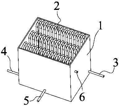
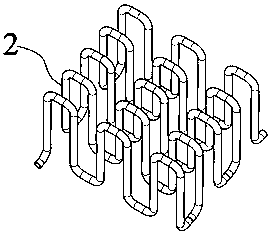
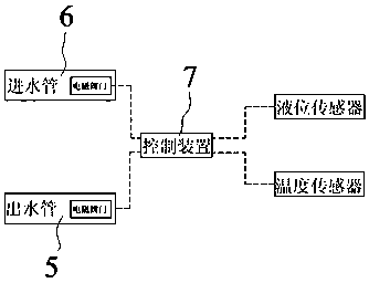
[0027] as attached figure 1 , attached figure 2 And attached image 3 The exhaust gas waste heat recovery device of this embodiment includes a water tank 1, a heat exchange pipe 2, an air intake pipe 3, an air outlet pipe 4, a water outlet pipe 5, a water inlet pipe 6, and a control device 7. The high-temperature exhaust gas passes through the air intake pipe 3 along the heat exchange pipe 2 Enter the water tank 1, the exhaust gas cooled by the heat exchange pipe 2 is discharged through the outlet pipe 4, and the high temperature exhaust gas in the water tank 1 fully contacts with the cooling water through the heat exchange pipe 2 to absorb the heat of the high temperature exhaust gas , the device has a simple structure and is easy to operate. By installing a heat exchange pipe 2 in the water tank 1, the high-temperature exhaust gas is fully contacted with water through the heat exchange pipe 2 and cooled to achieve the purpose of heat recovery.

[0028] The cooling water i...


PUM


Abstract

The invention relates to the technical field of white spirit brewing equipment, in particular to a waste heat recovery device. The device comprises a water tank, a heat exchange discharging pipe is arranged in the water tank, the two ends of the heat exchange discharging pipe communicate with an air inlet pipe and an air outlet pipe respectively, the high-temperature waste gas enters into the water tank through the air inlet pipe and along the heat exchange discharging pipe, after being cooled by the heat exchange discharging pipe, the waste gas is discharged out through the air outlet pipe, and the high-temperature waste gas in the water tank makes full contact with the cooling water through the heat exchange discharging pipe to achieve the effect of absorbing heat from the high-temperature waste gas. The device is simple in structure and convenient to operate, the heat exchange discharging pipe is arranged in the water tank, the high-temperature waste gas and the water are fully contacted to be cooled through the heat exchange discharging pipe, and thus the purpose of heat recovery is achieved.

Description

technical field [0001] The invention relates to the technical field of liquor brewing equipment, in particular to a waste gas waste heat recovery device. Background technique [0002] In the liquor brewing industry, liquor needs to be distilled to be separated from fermented and mature grains. The distillation process is the link that consumes the most energy in liquor production. At present, in most liquor production enterprises, the burner is used to heat the boiler to generate steam for distilling liquor; the burner generates a large amount of high-temperature exhaust gas during the heating process of the boiler, and the conventional high-temperature exhaust gas is directly discharged outside, taking away a lot of heat. As a result, the utilization rate of heat energy in the whole liquor distillation process is low. [0003] To sum up, there is an urgent need for exhaust gas waste heat recovery devices. Contents of the invention [0004] In view of the above problems,...

Claims


Application Information

Patent Timeline
Patent Type & Authority Applications(China)
IPC IPC(8): F28D7/08F28F27/00
CPCF28D7/082F28F27/00
Inventor 魏万坪
Owner 四川万家福酒业有限公司
Learn More