
Flue gas steam removing device and recycling method of residual heat of flue gas steam removing device

A flue gas and steam technology, applied in separation methods, chemical instruments and methods, lighting and heating equipment, etc., can solve the problems of slow flow rate, air pollution, small heat recovery, etc., to improve the treatment rate, increase the removal probability, The effect of saving resources

Pending Publication Date: 2017-07-14
张久明
View PDF9 Cites 0 Cited by
  • Summary
  • Abstract
  • Description
  • Claims
  • Application Information

AI Technical Summary

Problems solved by technology

[0002] At present, the air pollution and smog weather caused by the discharge of industrial waste gas and coal-fired flue gas have seriously damaged the ecological environment and affected human health.
We know that the existing dry dust removal technologies cannot desulfurize and denitrify. Although the wet flue gas purification technology can desulfurize and denitrify, the problem of dehydration is difficult to solve. A large amount of water vapor from the chimney is also a kind of "white" pollution and energy. Waste, and there are also phenomena of "gypsum rain" and "ammonia escape". Part of the pollutants that have been absorbed by the purification liquid, such as PM2.5, are discharged with water vapor, which is the cause of haze weather. one
[0003] As we all know, the flue gas also contains more heat. When the flue gas is released, it will also take away more heat. According to statistics, the heat of the flue gas is an important factor for the decline of the boiler efficiency, generally reaching 8-12%. Therefore, recovering flue gas heat is an important task for energy saving and emission reduction; generally, the flow velocity of flue gas in the flue gas pipeline is only about 4m / s. When the water vapor containing flue gas flows through the demister at a certain speed, due to the slow , the relative density per unit volume is small, the heat absorption efficiency of demisting is very low, and the heat recovery is very small, so it is urgent to produce a device for flue gas dehydration and waste heat recovery, so as to reduce energy loss

Method used


Image

  • Flue gas steam removing device and recycling method of residual heat of flue gas steam removing device
  • Flue gas steam removing device and recycling method of residual heat of flue gas steam removing device
  • Flue gas steam removing device and recycling method of residual heat of flue gas steam removing device

Examples


Embodiment Construction

[0019] The technical solutions in the embodiments of the present invention will be clearly and completely described below in conjunction with the accompanying drawings in the embodiments of the present invention. Obviously, the described embodiments are only a part of the embodiments of the present invention, rather than all the embodiments.

[0020] Examples of the embodiments are shown in the drawings, in which the same or similar reference numerals denote the same or similar elements or elements with the same or similar functions throughout. The embodiments described below with reference to the accompanying drawings are exemplary, and are intended to explain the present invention, but should not be construed as limiting the present invention.

[0021] In the description of the present invention, it should be understood that the terms "center", "longitudinal", "transverse", "length", "width", "thickness", "upper", "lower", "front", " "Back", "Left", "Right", "Vertical", "Horizont...


PUM


Abstract

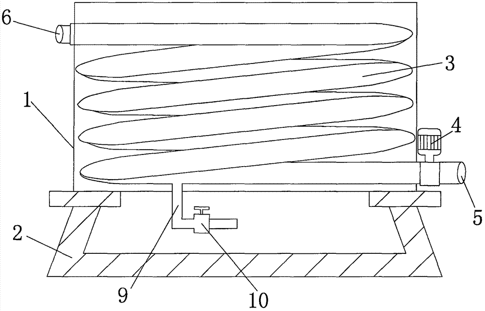
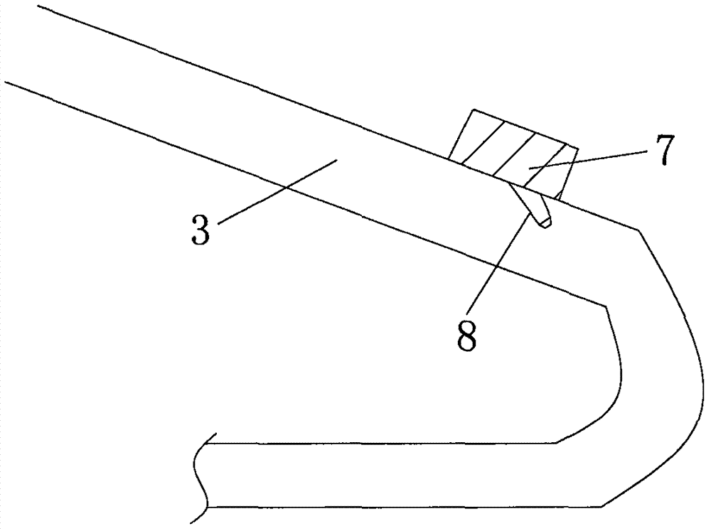
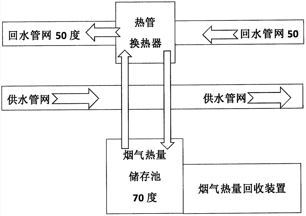
The invention discloses a flue gas steam removing device and a recycling method of residual heat of the flue gas steam removing device. The flue gas steam removing device comprises a housing, wherein a bracket is arranged at the lower end of the housing; a flue gas pipeline is arranged in the housing; the flue gas pipeline is divided into nine sections; each section of the flue gas pipeline is provided with a demister and each demister is provided with a fog-spraying nozzle; the fog-spraying nozzles are arranged on inner wall of the upper part of the flue gas pipeline; a head end direction of each fog-spraying nozzle is opposite to a flue gas flowing direction; a gas inlet is arranged at one side of the lower part of the housing; and a gas outlet is arranged at one side, far away from the gas inlet, of the upper part of the housing. According to the flue gas steam removing device, the demisters are arranged so that the opportunity that fog foam is collected is increased; the fog foam, which is not removed, is collected at the next turning part under the same action of the demister; a movement direction of the flowing flue gas is rapidly and continuously changed; and liquid drops in the flue gas are separated out rapidly under a joint action of an inertial force and gravity, so that the recycling efficiency of heat content of steam in the flue gas is greatly improved.

Description

Technical field [0001] The invention relates to the technical field of flue gas dehydration, in particular to a flue gas dehydration steam device and a method for recovering remaining heat. Background technique [0002] At present, the air pollution and haze caused by the discharge of industrial waste gas and coal-burning flue gas have severely damaged the ecological environment and affected human health. We know that various existing dry dust removal technologies cannot desulfurize and denitrify. Although wet flue gas purification technology can desulfurize and denitrify, the dehydration problem is more difficult to solve. The large amount of water vapor coming out of the chimney is also a kind of "white" pollution and energy. Waste, and there are also phenomena of "gypsum rain" and "ammonia escape". Some pollutants that have been absorbed by the purification fluid, such as PM2.5, are discharged with water vapor, which is the cause of the haze weather. one. [0003] As we all kn...

Claims


Application Information

Patent Timeline
IPC IPC(8): B01D45/06B01D45/02B01D45/16F23J15/00
CPCB01D45/02B01D45/06B01D45/16F23J15/006
Inventor 张久明
Owner 张久明
Learn More