
Fingerprint identification module, display device and electronic device

A fingerprint recognition module and display device technology, applied in character and pattern recognition, instruments, computer parts, etc., can solve the problems of bending fingerprint sensor chips, large fingerprint recognition area, outdoor stray light interference, etc.

Inactive Publication Date: 2019-01-29
GUANGDONG OPPO MOBILE TELECOMM CORP LTD
View PDF4 Cites 12 Cited by
  • Summary
  • Abstract
  • Description
  • Claims
  • Application Information

AI Technical Summary

Problems solved by technology

[0002] At present, the optical fingerprint recognition module can obtain fingerprint information by receiving the light signal reflected by the finger. Causes the fingerprint sensor chip to bend

Method used


Image

  • Fingerprint identification module, display device and electronic device
  • Fingerprint identification module, display device and electronic device
  • Fingerprint identification module, display device and electronic device

Examples


Embodiment Construction

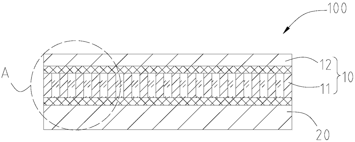
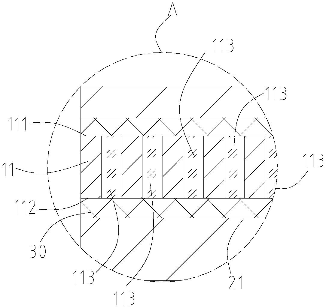
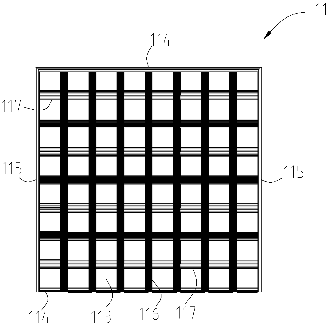
[0022] see figure 1 , the embodiment of the present application provides a fingerprint recognition module 100 , the fingerprint recognition module 100 includes a collimator 10 and a fingerprint sensor chip 20 . The collimator 10 includes a collimation layer 11 and a filter layer 12 plated on one side of the collimation layer 11, the filter layer 12 is used to filter light of a specific wavelength, and the fingerprint sensor chip 20 It is fixed on the side of the alignment layer 11 away from the filter layer 12 .

[0023] The filter layer 12 is plated on one side of the collimation layer 11, so that the collimation layer 11 carries the filter layer 12, and the filter layer 12 and the collimation layer 11 are composed of A collimation structure with a light filtering function, the above-mentioned collimation structure can filter stray light of a specific wavelength, to avoid stray light from interfering with the normal operation of the fingerprint sensor chip 20, so that there ...


PUM


Abstract

The invention provides a fingerprint identification module, a display device and an electronic device. The fingerprint identification module comprises a collimator and a fingerprint sensing chip, wherein the collimator comprises a collimating layer and a filter layer plated on one side of the collimating layer, and the fingerprint sensing chip is fixed on one side of the collimating layer oppositeto the filter layer or on one side of the filter layer opposite to the collimating layer. The collimating structure can filter stray light of a specific wavelength to avoid stray light interfering with the normal operation of the fingerprint sensing chip, so that a filter coating is not required on the fingerprint sensing chip and the fingerprint sensing chip is prevented from bending under a force.

Description

technical field [0001] The present application relates to the technical field of electronic equipment, in particular to a fingerprint identification module, a display device and electronic equipment. Background technique [0002] At present, the optical fingerprint recognition module can obtain fingerprint information by receiving the light signal reflected by the finger. Causes the fingerprint sensor chip to bend. Contents of the invention [0003] An embodiment of the present application provides a fingerprint recognition module, the fingerprint recognition module includes a collimator and a fingerprint sensor chip, the collimator includes a collimation layer and a filter plated on one side of the collimation layer In the optical layer, the fingerprint sensor chip is fixed on the side of the alignment layer away from the filter layer, or fixed on the side of the filter layer away from the alignment layer. [0004] An embodiment of the present application further provid...

Claims


Application Information

Patent Timeline
Patent Type & Authority Applications(China)
IPC IPC(8): G06K9/00
CPCG06V40/1324
Inventor 袁石林
Owner GUANGDONG OPPO MOBILE TELECOMM CORP LTD
Learn More