Suspension device for flat cables with anti-rope lock pins on the sliding frame of line poles and towers

A technology of suspension device and tower sliding frame, which is applied in the direction of cable suspension device, cable installation, overhead installation, etc., which can solve the problems of insufficient protection, tearing of internal copper wires, and cost etc.

Active Publication Date: 2020-10-23
嘉兴倍创网络科技有限公司
View PDF4 Cites 0 Cited by
  • Summary
  • Abstract
  • Description
  • Claims
  • Application Information

AI Technical Summary

Problems solved by technology

[0004] Aiming at the deficiencies in the prior art, the purpose of the present invention is to provide a suspension device for flat cables on the pole tower carriage with anti-rope lock pins, so as to solve the problem that flat cables are often hung together in rows, suspended, pulled, moved, and installed on the line pole tower. At this time, different from the conventional line, the flat cable needs sufficient horizontal space for laying. When the roller of the hanger winds the flat cable, it will intuitively cause the horizontal laying line to be squeezed and flanged by the left and right limit shells. The wire tube is twisted into one body under tension, and the outer wire tube is easily pulled by the tension to tighten the wire tube sleeve, so that the inner copper wire is torn by the New Pull, causing a short circuit of a single wire tube and requiring the replacement of the whole wire tube, which makes the suspension operation Costly and insufficient protection

Method used


Image

  • Suspension device for flat cables with anti-rope lock pins on the sliding frame of line poles and towers
  • Suspension device for flat cables with anti-rope lock pins on the sliding frame of line poles and towers
  • Suspension device for flat cables with anti-rope lock pins on the sliding frame of line poles and towers

Examples


Embodiment Construction

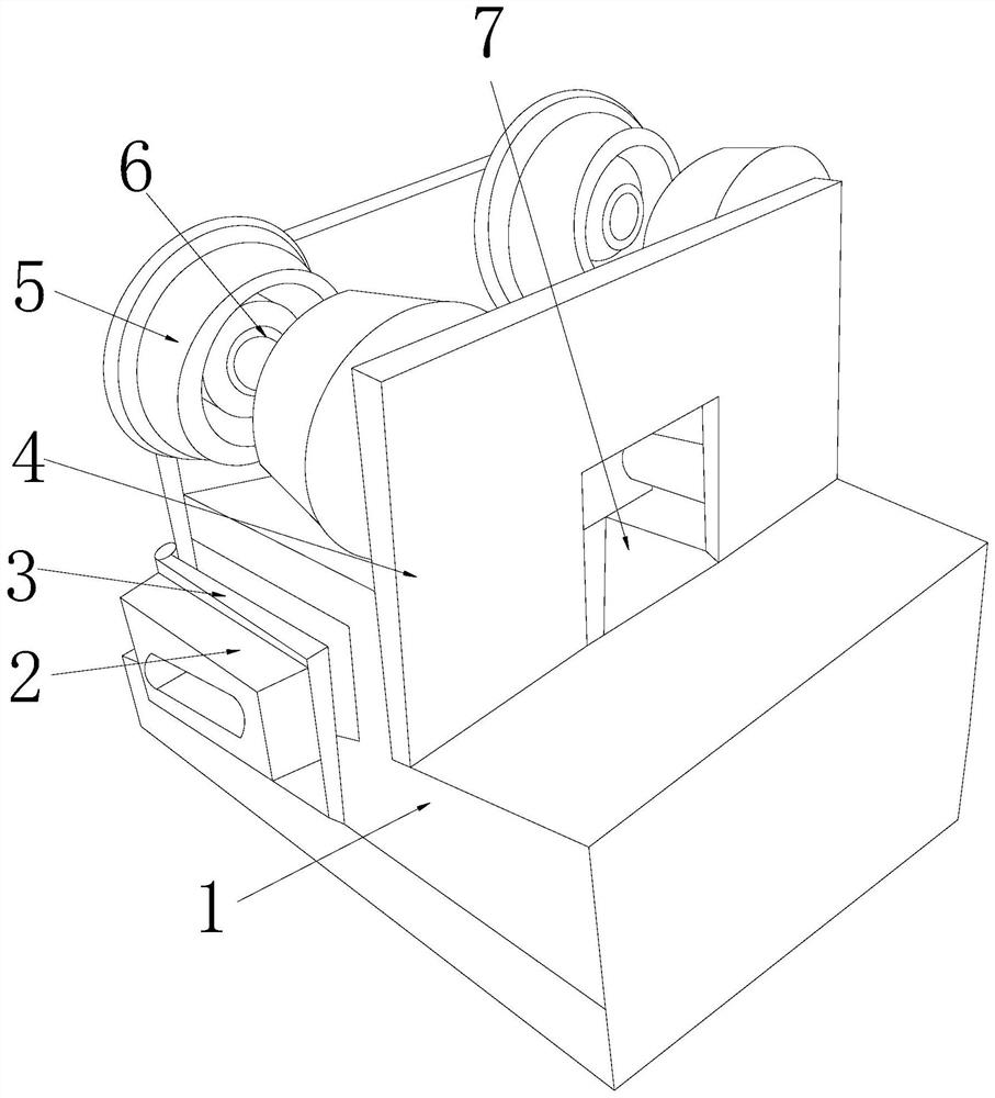
[0027] In order to make the technical means, creative features, goals and effects achieved by the present invention easy to understand, the present invention will be further described below in conjunction with specific embodiments.

[0028] see Figure 1-Figure 7, the present invention provides a suspension device for a flat row of cables on a line pole tower carriage with anti-rope locking pins, its structure includes: anti-rope clamping box seat 1, cable tightening groove 2, hinge cover plate 3, rail clamping vertical plate 4. The rubber wheel housing 5, the bearing column 6, and the observation slot 7. The clamping rail vertical plate 4 is provided with two and respectively attached to the left and right sides of the projection on the top of the anti-rope clamping box seat 1. The bearing The column 6 is installed inside the rubber wheel housing 5 and the axes are collinear. The rubber wheel housing 5 is mechanically connected to the top of the clamping rail vertical plate 4...


PUM


Abstract

The invention discloses an anti-rope lock pin suspension device for flat cables on a line tower sliding frame, which structure comprises an anti-rope line clamping box base, a cable tightening groove,a hinge cover plate, rail clamping vertical plates, a rubber wheel shell, a bearing column and an observation groove, wherein there are two rail clamping vertical plates, the two rail clamping vertical plates are respectively attached to the left and right sides of a convex block on the top of the anti-rope line clamping box base. According to the invention, the coordination of the anti-rope lineclamping box base and the cable tightening groove is applied, the flat cables are inserted into horizontally arranged grooves and get into a hoisting and winding box after the head and tail ends being tightened, a winding pin rod is enabled to subjected to friction and push of cable tubes to rotate so as to drive the cables to be reversely wound and output or transversely run through and output,and the cable tubes are clamped one by one through a corrugated groove clamping plate during the process so as to enable transverse lines to be interlocked and get close to the pin surface when the cable tubes are suspended, thereby achieving an effect of winding and laying the cables. The device avoids the extrusion of flanging in the suspension moving process, avoids the line slippage and deformation and also effectively protects the toughness quality of the outer shell of the cable tubes.

Description

technical field [0001] The invention relates to a suspension device for a flat row cable with a reverse rope lock pin on a sliding frame of a line pole and a tower, and belongs to the field of cable suspension equipment. Background technique [0002] The cables on the poles are divided into circular thick-diameter bundled tube lines and horizontal tube-by-tube parallel cables. Flat cables are commonly used in densely populated areas, which is convenient for the birds to reserve space for passing between lines in the air. Caliber beam tube lines are mostly used for beam-type long-path power transmission operations. There is a significant difference between the suspension and mobile hoisting of the two lines on the line pole tower, that is, the horizontal area of ​​the flat cable is too large, and it is more troublesome to hang. The shortcomings of the current technology that need to be optimized are: [0003] Flat cables are often hung together in rows, suspended, pulled, mov...

Claims


Application Information

Patent Timeline
Patent Type & Authority Patents(China)
IPC IPC(8): H02G7/05
CPCH02G7/053
Inventor 戴宝木
Owner 嘉兴倍创网络科技有限公司
Why Eureka
Try Eureka