A bionic transpiration cooling adaptive radiator
An adaptive radiator technology, applied in the field of heat dissipation, can solve the problems of large space occupation, high cost, complex liquid cooling radiator system, etc., to achieve the effect of improving space, improving work performance, and ensuring long-term efficient and stable operation
- Summary
- Abstract
- Description
- Claims
- Application Information
AI Technical Summary
Problems solved by technology
Method used
Image
Examples
Embodiment example 1
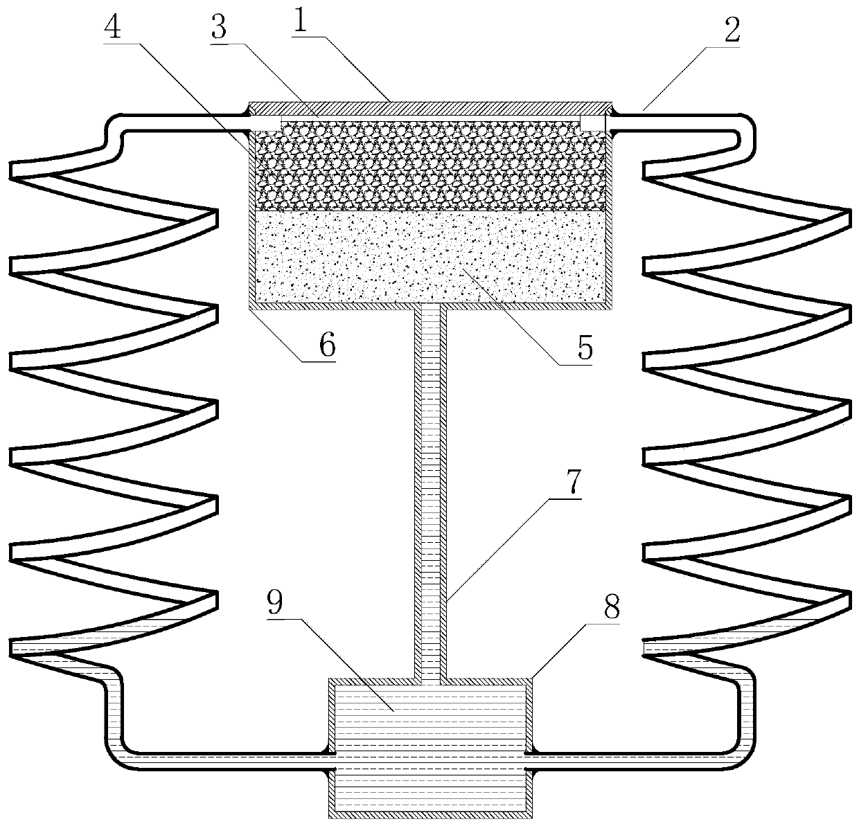
[0039] Such asfigure 1 and figure 2 As shown, the circulating working circuit of the present disclosure is composed of an evaporation chamber (including the upper cover plate 1 of the evaporation chamber and the shell 6 of the evaporation chamber), a vapor circulation pipeline 2, a liquid storage chamber 8 and a connecting capillary 7 connecting the liquid storage chamber and the evaporation chamber. , the bionic porous material 4, the filling fiber 5 and the working liquid 9 are also installed in the circulating working loop.
[0040] The upper cover plate 1 of the evaporation chamber can be made of a copper plate with good thermal conductivity to reduce heat transfer resistance. The thickness of the copper plate is about 6mm, and the size of the copper plate is selected according to the actual heat dissipation area required. The upper cover plate 1 is directly bonded to the electronic device that needs to dissipate heat, and the heat generated by the electronic device is d...
Embodiment example 2
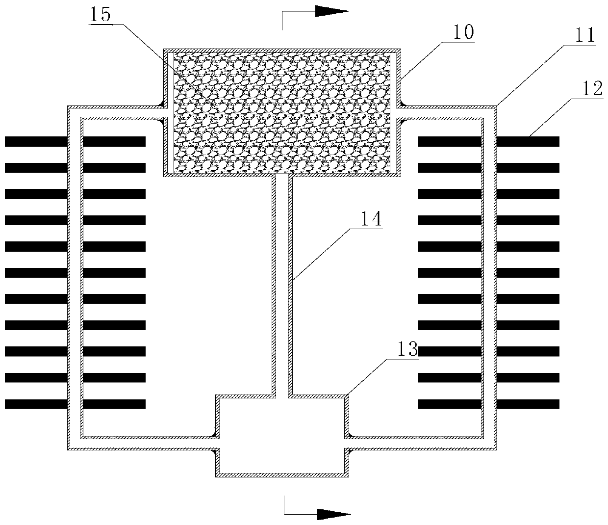
[0047] Implementation Case 2 has the same structural principle as Implementation Case 1. The difference is that Implementation Case 1 is installed vertically. Considering that the vertical space may be insufficient for specific applications, Design Implementation Case 2 is designed for horizontal placement.
[0048] Such as image 3 and Figure 4 As shown, this case includes an evaporation chamber 10 , a steam circulation pipeline 11 , auxiliary cooling fins 12 , a liquid storage chamber 13 , a connecting pipe 14 , a bionic porous material 15 , filling fibers 17 and a steam channel 16 .
[0049] The difference between the structure of the evaporation chamber 10 in this embodiment and the first embodiment is that there is no steam channel on the upper cover plate, and the steam channel 16 is on the bionic porous material 15 , which is completed when the bionic porous material 15 is sintered.
[0050] The circulating steam pipeline 11 is designed as a straight pipeline, and an ...
Embodiment example 3
[0054] The operating principle and internal structure of this embodiment are exactly the same as those of Embodiments 1 and 2 and will not be described again. The difference is that this embodiment is designed independently for three channels.
[0055] Such as Figure 5 and Image 6 shown. This embodiment includes a circulating steam pipe cooling pipe 18 , a liquid storage pipe 19 , a circulating steam pipe connecting pipe 20 , a steam channel 21 , an evaporation chamber 22 and a connecting section 23 .
[0056] The steam channel 21, the circulating steam pipe cooling pipe 18, the liquid storage pipe 19 and the circulating steam pipe connecting pipe 20 form an independent steam circulation circuit. This embodiment includes three independent and symmetrically distributed cooling cycles, and each cycle can work independently .
[0057] The evaporation chamber 22 is cylindrical and filled with fibers and biomimetic porous material inside, and three steam channels 21 are opened...
PUM
 Abstract
Description
Claims
Application Information
 - R&D
- Intellectual Property
- Life Sciences
- Materials
- Tech Scout
- Unparalleled Data Quality
- Higher Quality Content
- 60% Fewer Hallucinations
Browse by: Latest US Patents, China's latest patents, Technical Efficacy Thesaurus, Application Domain, Technology Topic, Popular Technical Reports.
© 2025 PatSnap. All rights reserved.Legal|Privacy policy|Modern Slavery Act Transparency Statement|Sitemap|About US| Contact US: help@patsnap.com


