
Flue gas purification system for power plant

A flue gas purification system and technology for power plants, which are applied in gas treatment, chemical instruments and methods, combined devices, etc., can solve the problems of unreasonable flue gas flow field design, high operating costs, and high energy consumption, and achieve low cost, easy availability and application. The effect of reducing the cost of dust removal and the simple structure of the equipment

Inactive Publication Date: 2019-02-01
刘鹏
View PDF0 Cites 9 Cited by
  • Summary
  • Abstract
  • Description
  • Claims
  • Application Information

AI Technical Summary

Problems solved by technology

The current power plants generally deal with flue gas for a single pollutant, resulting in complex structure of the smoke removal system, high energy consumption, high investment and operating costs, and poor flue gas treatment effect
There is a lack of overall planning among the various treatment systems, and the design of the flue gas flow field is unreasonable, resulting in high overall energy consumption. There is a margin between each system, and there are many interface restrictions, resulting in unreasonable design of upstream and downstream systems and devices, and difficult processing. Large, and to achieve the same processing efficiency, large investment, large footprint, high operating costs, poor reliability

Method used


Image

  • Flue gas purification system for power plant
  • Flue gas purification system for power plant
  • Flue gas purification system for power plant

Examples


Embodiment Construction

[0022] The specific implementation manner of the present invention will be further described below in conjunction with the accompanying drawings. Wherein the same components are denoted by the same reference numerals.

[0023] It should be noted that the words "front", "rear", "left", "right", "upper" and "lower" used in the following description refer to the directions in the drawings, and the words "inner" and "outer ” refer to directions towards or away from the geometric center of a particular part, respectively.

[0024] In order to make the content of the present invention more clearly understood, the technical solutions in the embodiments of the present invention will be clearly and completely described below in conjunction with the drawings in the embodiments of the present invention.

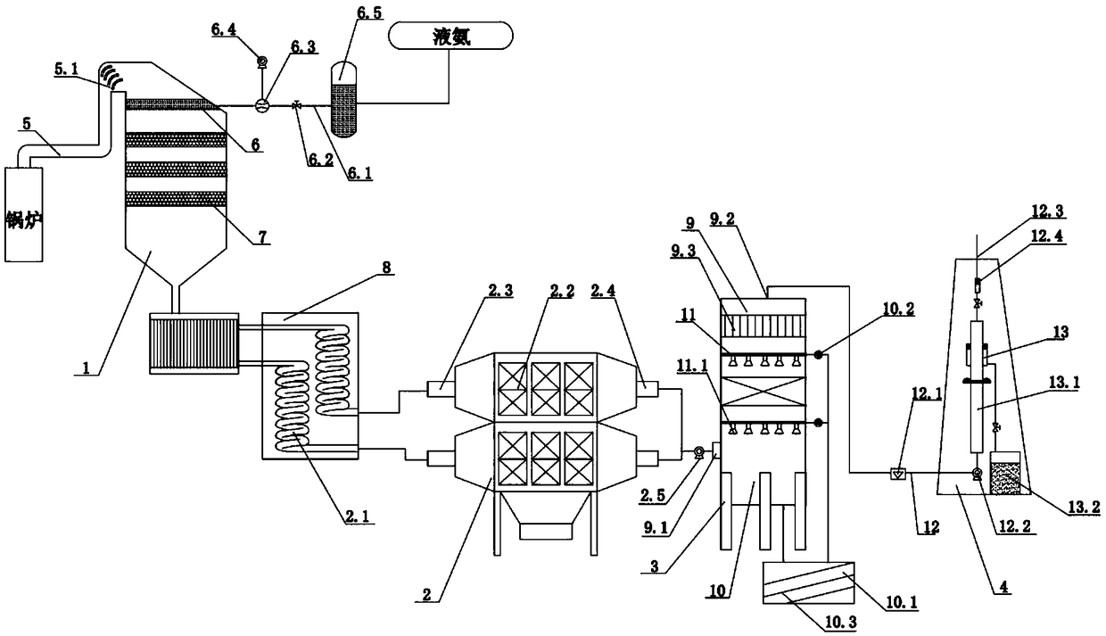
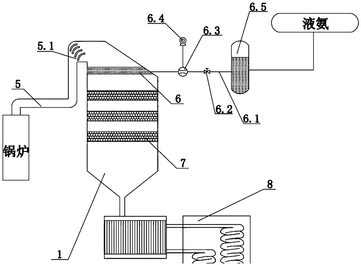
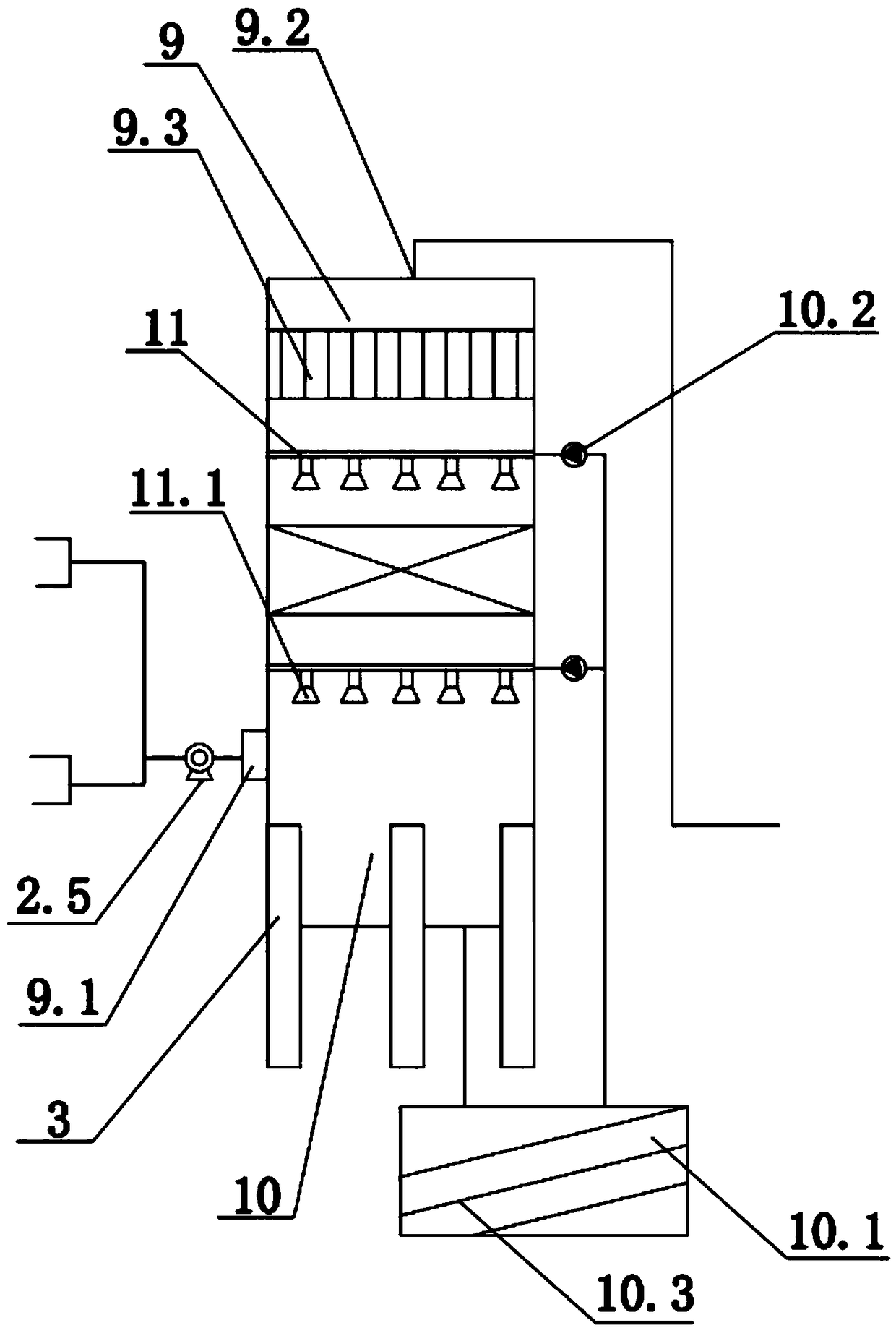
[0025] As shown in the figure, a flue gas purification system for a power plant includes a conveying pipeline, which has a streamlined structure to reduce resistance, and several defle...


PUM


Abstract

The invention discloses a flue gas purification system for a power plant. The flue gas purification system comprises a conveying pipeline which is sequentially communicated with a denitration reactiondevice, a dust removal device, a desulfurization system and a chimney. An inlet flue is arranged on the denitration reaction device, the dust removal device comprises a dust removal pipe and an electrostatic precipitator and bag filter, the desulfurization system comprises a desulfurization tower, a flue gas inlet and a flue gas outlet, the bottom of the chimney is connected with the flue gas outlet through an exhaust pipe, and an exhaust port is formed in the top of the chimney. Flue gas is more uniformly distributed by the aid of guide vanes and rectified by a rectifier grille; waste heat in the flue gas is recovered by a heat exchanger; the electrostatic and bag composite dust removal device combines the advantages of electric dust removal and bag dust removal and is high in dust removal efficiency and low in dust removal cost; used alkaline liquid is low in cost, easy to obtain and wide in applicable range, and the sprayed alkaline liquid contacting with the flue gas returns intoan alkaline liquid treatment tank and is subjected to reduction regeneration treatment, preliminarily filtered by a filter plate, sprayed out by a spray pipe and recycled.

Description

technical field [0001] The invention relates to the technical field of power plant flue gas treatment, in particular to a power plant flue gas purification system. Background technique [0002] With the progress of society and the development of science and technology, power plants occupy an increasingly important position in the entire national economy. However, the environmental problems caused by power plant flue gas make people feel worried. A good environment is the guarantee of people's healthy life, and protecting the environment is everyone's duty. The current power plants generally treat the flue gas only for a single pollutant, resulting in complex structure of the smoke removal system, high energy consumption, high investment and operating costs, and poor flue gas treatment effect. There is a lack of overall planning among the various treatment systems, and the design of the flue gas flow field is unreasonable, resulting in high overall energy consumption. There ...

Claims


Application Information

Patent Timeline
Patent Type & Authority Applications(China)
IPC IPC(8): B01D53/86B01D53/56B01D53/78B01D53/50B01D50/00
CPCB01D53/8628B01D50/00B01D53/50B01D53/78B01D2258/0283
Inventor 刘鹏巩玉苹
Owner 刘鹏
Learn More