Straw bundling instrument

A technology of equipment and straw, which is applied in the field of straw binding equipment, can solve the problems of easy loosening of straps, high labor cost, poor knotting effect, etc., and achieve the effect of good reset and convenient knotting

Active Publication Date: 2019-02-01
时平元
View PDF9 Cites 8 Cited by
  • Summary
  • Abstract
  • Description
  • Claims
  • Application Information

AI Technical Summary

Problems solved by technology

[0003] In order to overcome the disadvantages that there are many straws, one person needs to hold down the straws, and the other person knots the straps, so the labor cost is high, and the straps are easy to loosen during knotting, resulting in poor knotting effect, the technical problem of the present invention : To provide a straw binding device that can fix the straps to facilitate people to bundle straws, reduce labor costs, and avoid knotting caused by loose straps

Method used


Image

  • Straw bundling instrument
  • Straw bundling instrument
  • Straw bundling instrument

Examples


Embodiment 1

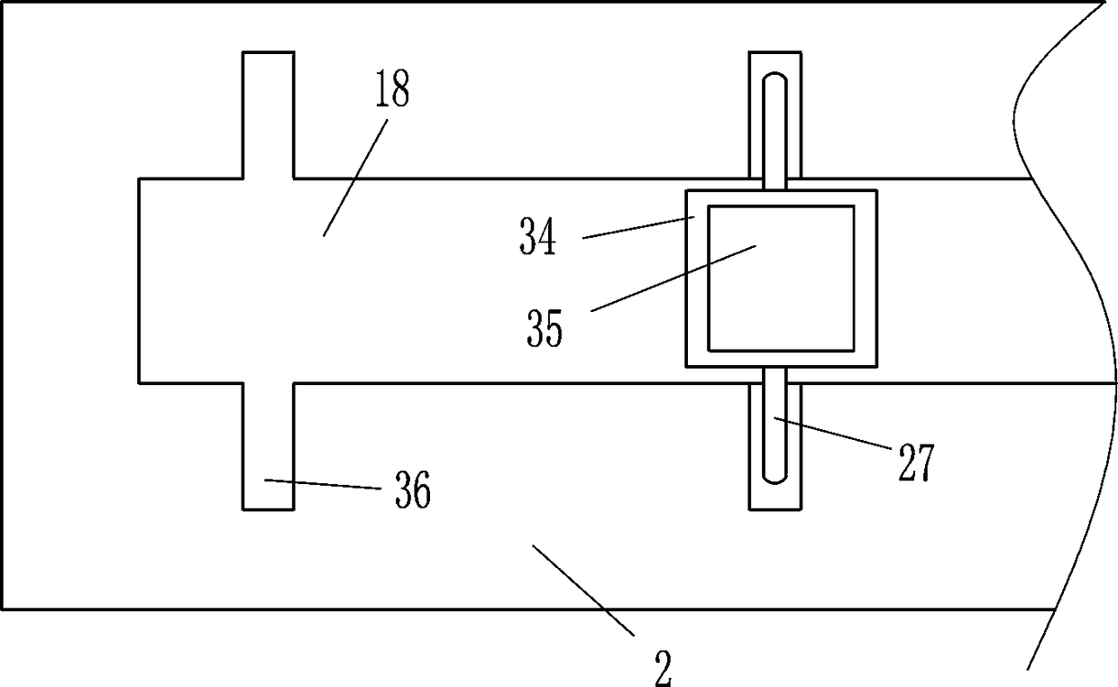
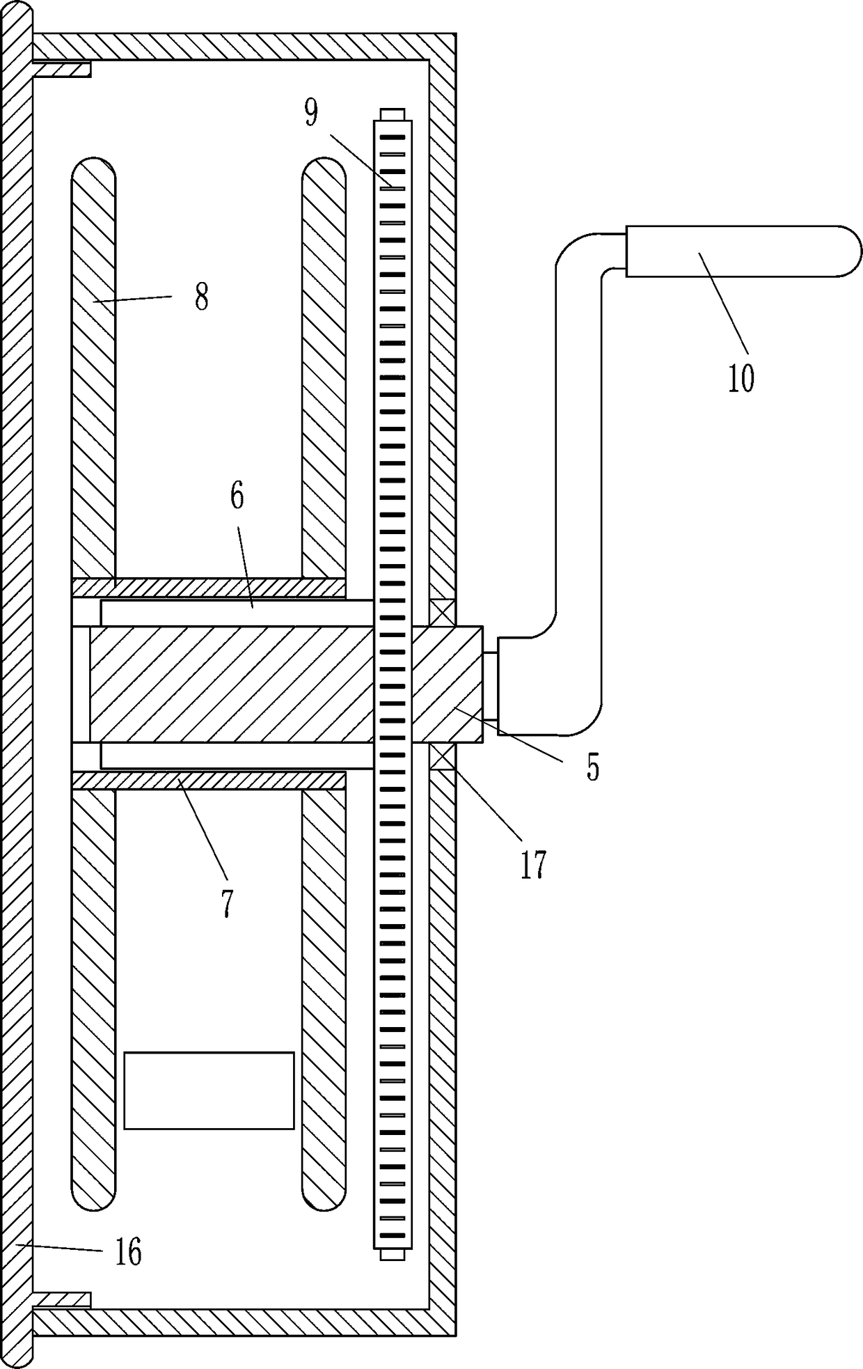
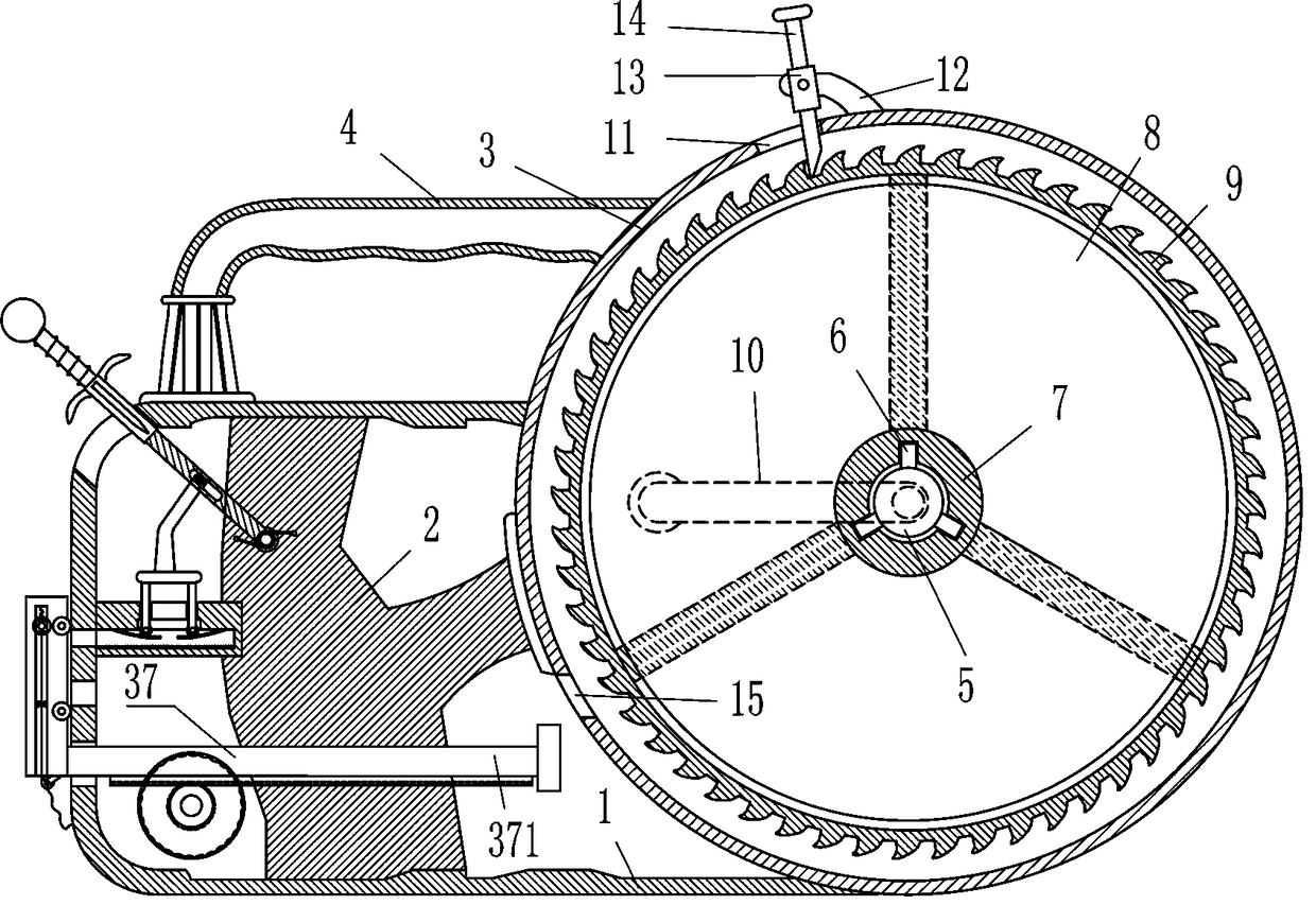
[0020] A straw binding device, such as Figure 1-4As shown, it includes a frame body 1, a support plate 2, a circular frame 3, a handle 4, a rotating shaft 5, a block 6, a sleeve 7, a disc 8, a ratchet 9, a rocker 10, a support rod 12, and a guide sleeve 13 , card rod 14, threaded disc 16, first bearing seat 17, first sleeve 21, toothed strip 22, elastic plate 23, guide rod 25, contact wheel 26, inserting rod 27, horizontal plate 28, rectangular rod 29, Roller 31, connecting rod 32, torsion spring 33, rectangular sleeve 34 and grip bar 35, the right side of frame body 1 is fixed with circular frame 3, and the center of circular frame 3 is embedded with a first bearing Seat 17, the rotating shaft 5 is connected with the inner bearing of the first bearing seat 17, the rocker 10 is fixedly connected with the rear end of the rotating shaft 5, the front part of the rotating shaft 5 is fixedly connected with blocks 6 evenly spaced, and the sleeve 7 is sleeved on the front part of th...

Embodiment 2

[0022] A straw binding device, such as Figure 1-4 As shown, it includes a frame body 1, a support plate 2, a circular frame 3, a handle 4, a rotating shaft 5, a block 6, a sleeve 7, a disc 8, a ratchet 9, a rocker 10, a support rod 12, and a guide sleeve 13 , card rod 14, threaded disc 16, first bearing seat 17, first sleeve 21, toothed strip 22, elastic plate 23, guide rod 25, contact wheel 26, inserting rod 27, horizontal plate 28, rectangular rod 29, Roller 31, connecting rod 32, torsion spring 33, rectangular sleeve 34 and grip bar 35, the right side of frame body 1 is fixed with circular frame 3, and the center of circular frame 3 is embedded with a first bearing Seat 17, the rotating shaft 5 is connected with the inner bearing of the first bearing seat 17, the rocker 10 is fixedly connected with the rear end of the rotating shaft 5, the front part of the rotating shaft 5 is fixedly connected with blocks 6 evenly spaced, and the sleeve 7 is sleeved on the front part of t...

Embodiment 3

[0025] A straw binding device, such as Figure 1-4 As shown, it includes a frame body 1, a support plate 2, a circular frame 3, a handle 4, a rotating shaft 5, a block 6, a sleeve 7, a disc 8, a ratchet 9, a rocker 10, a support rod 12, and a guide sleeve 13 , card rod 14, threaded disc 16, first bearing seat 17, first sleeve 21, toothed strip 22, elastic plate 23, guide rod 25, contact wheel 26, inserting rod 27, horizontal plate 28, rectangular rod 29, Roller 31, connecting rod 32, torsion spring 33, rectangular sleeve 34 and grip bar 35, the right side of frame body 1 is fixed with circular frame 3, and the center of circular frame 3 is embedded with a first bearing Seat 17, the rotating shaft 5 is connected with the inner bearing of the first bearing seat 17, the rocker 10 is fixedly connected with the rear end of the rotating shaft 5, the front part of the rotating shaft 5 is fixedly connected with blocks 6 evenly spaced, and the sleeve 7 is sleeved on the front part of t...


PUM


Abstract

The invention relates to a bundling instrument, in particular to a straw bundling instrument. According to the straw bundling instrument, a bandage can be fixed, straw can be bundled conveniently, thelabor cost is reduced, and the situation that the knotting is affected due to loosening of the bandage is avoided. According to the technical scheme, the straw bundling instrument comprises a frame body, a supporting plate, a round frame, a handle, a rotating shaft, clamping blocks, a casing pipe, a disc, a ratchet wheel, a rocker, a supporting rod, a guide sleeve, a clamping rod, a threaded disc, a first bearing seat and the like; the round frame is fixedly connected to the right side of the frame body, the circle center of the round frame is fixedly connected with the first bearing seat inan embedded mode, and the rotating shaft is connected with a bearing in the first bearing seat. According to the straw bundling instrument, the bandage winds the casing pipe, and the handle is held, so that the bandage can be pulled to bundle the straw; and the binding head end is fixed through the device, the rocker is rocked and reversely rotated to enable the straw to be bundled, and the strawcan be clamped through a pressing device, so that an operator can better bundle the straw.

Description

technical field [0001] The invention relates to a binding device, in particular to a straw binding device. Background technique [0002] In agriculture, a large amount of straw will appear after the processing of corn or wheat. The straw can be collected and used in other places. Generally, the straw is bound with straps for collection. When people use straps to bundle the straw, due to the comparison of straw If there are too many, one person needs to hold down the straw, and the other person needs to tie the strap. This is a high labor cost, and the strap is easy to loosen during knotting, which leads to poor knotting effect. Therefore, people use tools to fix the straw and then fix it. The straps are knotted, so the operation is cumbersome. Contents of the invention [0003] In order to overcome the disadvantages that there are many straws, one person needs to hold down the straws, and the other person knots the straps, so the labor cost is high, and the straps are eas...

Claims


Application Information

Patent Timeline
Patent Type & Authority Applications(China)
IPC IPC(8): B65B13/04B65B13/18B65B13/26
CPCB65B13/04B65B13/18B65B13/26
Inventor 陈翠
Owner 时平元
Why Eureka
Try Eureka