Air seal machine with anti-blocking mechanism

An air lock and anti-blocking technology, which is applied in the field of air lock, can solve the problems of affecting the rotation of the impeller, affecting the service life of the air lock, and affecting the working efficiency of the air lock, so as to achieve the effect of prolonging the service life and improving the working efficiency

Pending Publication Date: 2019-02-01
郑州金诚信筛网设备有限公司
View PDF0 Cites 1 Cited by
  • Summary
  • Abstract
  • Description
  • Claims
  • Application Information

AI Technical Summary

Problems solved by technology

However, during use, the material entering the dust collector is mixed with many flaky or fibrous sundries besides fine dust, such as hair, thin wires, etc. These sundries are easy to get stuck on the air lock blad

Method used


Image

  • Air seal machine with anti-blocking mechanism
  • Air seal machine with anti-blocking mechanism
  • Air seal machine with anti-blocking mechanism

Examples


Embodiment 1

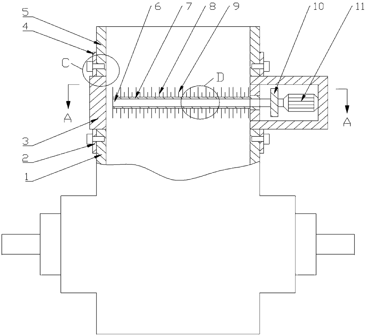
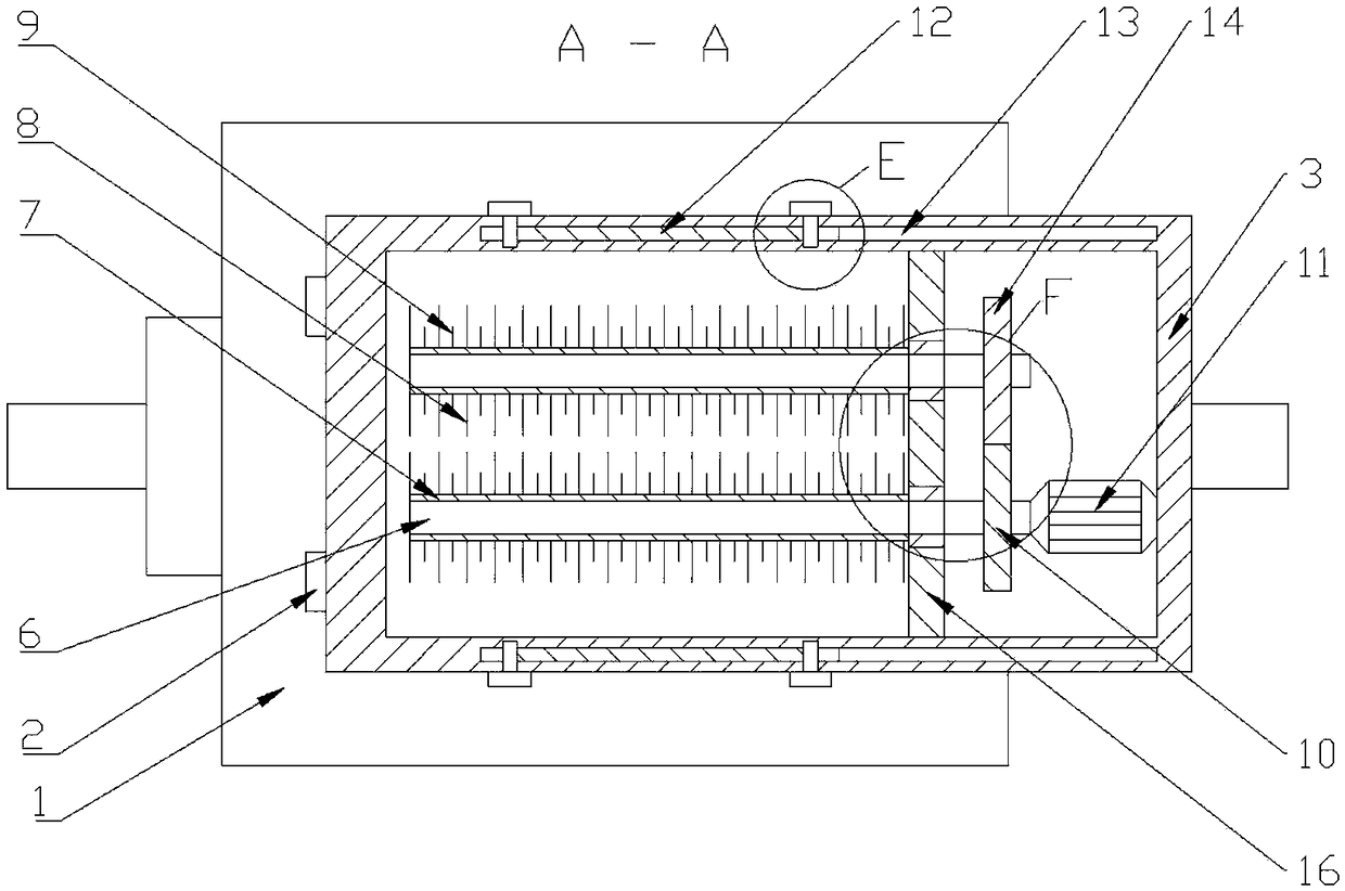
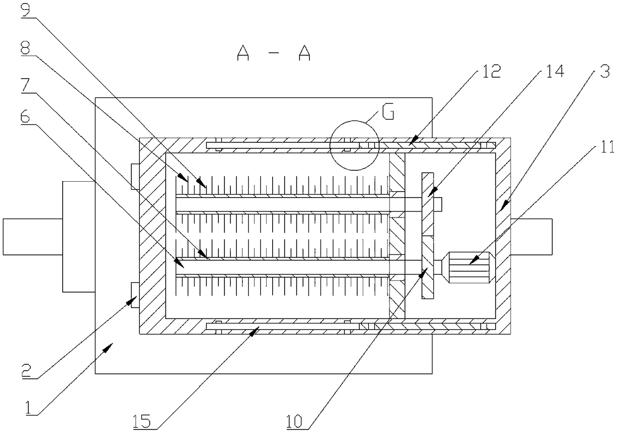
[0040] Such as Figure 1-11 As shown, an air shutoff device with an anti-blocking mechanism includes a casing 1 and a feeding pipe 5, the feeding pipe 5 is installed on the upper end of the casing 1, and an anti-blocking mechanism is provided between the casing 1 and the feeding pipe 5. The anti-blocking mechanism includes the anti-blocking box 3 that the inside is provided with a partition 16. A motor 11 is installed on the side wall of the anti-blocking box 3. A No. 1 gear 10 is installed on the motor shaft of the motor 11. The No. 1 gear 10 is connected with the No. 1 gear. The No. 2 gear 14 meshed with the gear 10, the No. 1 gear 10 and the No. 2 gear 14 are all connected to the rotating shaft 6 passing through the partition 16 in the horizontal direction. The outer surface of 7 is provided with anti-blocking needle 8, the distance between two adjacent anti-blocking needles 8 is greater than the maximum cross-sectional diameter of the material, and the anti-blocking box 3 co...

Embodiment 2

[0043] Such as Figure 1-11 As shown, an air shutoff device with an anti-blocking mechanism includes a casing 1 and a feeding pipe 5, the feeding pipe 5 is installed on the upper end of the casing 1, and an anti-blocking mechanism is provided between the casing 1 and the feeding pipe 5. The anti-blocking mechanism includes the anti-blocking box 3 that the inside is provided with a partition 16. A motor 11 is installed on the side wall of the anti-blocking box 3. A No. 1 gear 10 is installed on the motor shaft of the motor 11. The No. 1 gear 10 is connected with the No. 1 gear. The No. 2 gear 14 meshed with the gear 10, the No. 1 gear 10 and the No. 2 gear 14 are all connected to the rotating shaft 6 passing through the partition 16 in the horizontal direction. The outer surface of 7 is provided with anti-blocking needle 8, the distance between two adjacent anti-blocking needles 8 is greater than the maximum cross-sectional diameter of the material, and the anti-blocking box 3 ...

Embodiment 3

[0048] Such as Figure 1-11 As shown, an air shutoff device with an anti-blocking mechanism includes a casing 1 and a feeding pipe 5, the feeding pipe 5 is installed on the upper end of the casing 1, and an anti-blocking mechanism is provided between the casing 1 and the feeding pipe 5. The anti-blocking mechanism includes the anti-blocking box 3 that the inside is provided with a partition 16. A motor 11 is installed on the side wall of the anti-blocking box 3. A No. 1 gear 10 is installed on the motor shaft of the motor 11. The No. 1 gear 10 is connected with the No. 1 gear. The No. 2 gear 14 meshed with the gear 10, the No. 1 gear 10 and the No. 2 gear 14 are all connected to the rotating shaft 6 passing through the partition 16 in the horizontal direction. The outer surface of 7 is provided with anti-blocking needle 8, the distance between two adjacent anti-blocking needles 8 is greater than the maximum cross-sectional diameter of the material, and the anti-blocking box 3 ...


PUM


Abstract

The invention relates to the technical field of an air seal machine, in particular to an air seal machine with an anti-blocking mechanism. The air seal machine with the anti-blocking mechanism comprises a gear No. 1, a gear No.2, a shell and a feeding pipe, wherein the anti-blocking mechanism with an anti-blocking box is arranged between the shell and the feeding pipe; the gear No. 1 and the gearNo.2 are both connected a rotating shaft passing through a baffle plate in a horizontal direction; a dust collection cover is sleeved on the outer surface of the rotating shaft; anti-blocking needlesare arranged on the outer surface of the dust collection cover; the distance between the two adjacent anti-blocking needles is greater than the diameter of the maximum cross section of a material; andthe anti-blocking box communicates with the interiors of the shell and the feeding pipe. By arranging the anti-blocking mechanism between the shell and the feeding pipe, the material fed in from thefeeding pipe firstly passes through the anti-blocking needles in the anti-blocking mechanism, so that sheet-like or fibrous sundries in the material such as hair and thin lines is wound on the anti-blocking needles, so as not to seriously affect the rotation of impellers, thus, the working efficiency of the air seal machine is improved, and the service life of the air seal machine is prolonged.

Description

technical field [0001] The invention relates to the technical field of air locks, in particular to an air lock with an anti-blocking mechanism. Background technique [0002] The air shutoff device is also called shut off fan, unloading valve, ash unloading valve, star unloader, the air shutoff device is an important equipment in the pneumatic conveying and ventilation dust removal network, its main function is to remove the The material is continuously and timely discharged, while ensuring that the pressure inside the equipment is not exposed to the normal pressure environment. It is widely used in the pneumatic transportation of equipment in rice milling, milling, feed, machinery and chemical industry, medicine, tobacco, metallurgy, cement and dust removal, and the unloading of pipe network pressure. For powder under positive pressure and negative pressure Shaped, granular, flake and fibrous materials play the role of continuous discharge and air tightness. [0003] The a...

Claims


Application Information

Patent Timeline
IPC IPC(8): B65G53/46
CPCB65G53/4625
Inventor 管旭
Owner 郑州金诚信筛网设备有限公司
Why Eureka
Try Eureka