A distributor and clarifier

A distributor, part of the technology, applied in the field of water treatment, can solve the problem of stirring for a long time

Active Publication Date: 2020-10-27
BGT GRP CO LTD
View PDF2 Cites 0 Cited by
  • Summary
  • Abstract
  • Description
  • Claims
  • Application Information

AI Technical Summary

Problems solved by technology

[0006] However, the problem with both of the above two high-efficiency clarifiers is that the dosing process uses a straight-through injection of the dosing pipe, and the primary concentration of the medicine during injection requires a stirring device for a long time
However, the distributor is to let the slurry evenly fall into the tank after flocculation, and the distributor is simply to set a number of distribution holes

Method used


Image

  • A distributor and clarifier
  • A distributor and clarifier
  • A distributor and clarifier

Examples


Embodiment 1

[0050] This embodiment discloses a dispenser, and the whole and / or part of the content of preferred implementations of other embodiments may be used as a supplement to this embodiment under the condition that no conflict or contradiction is caused.

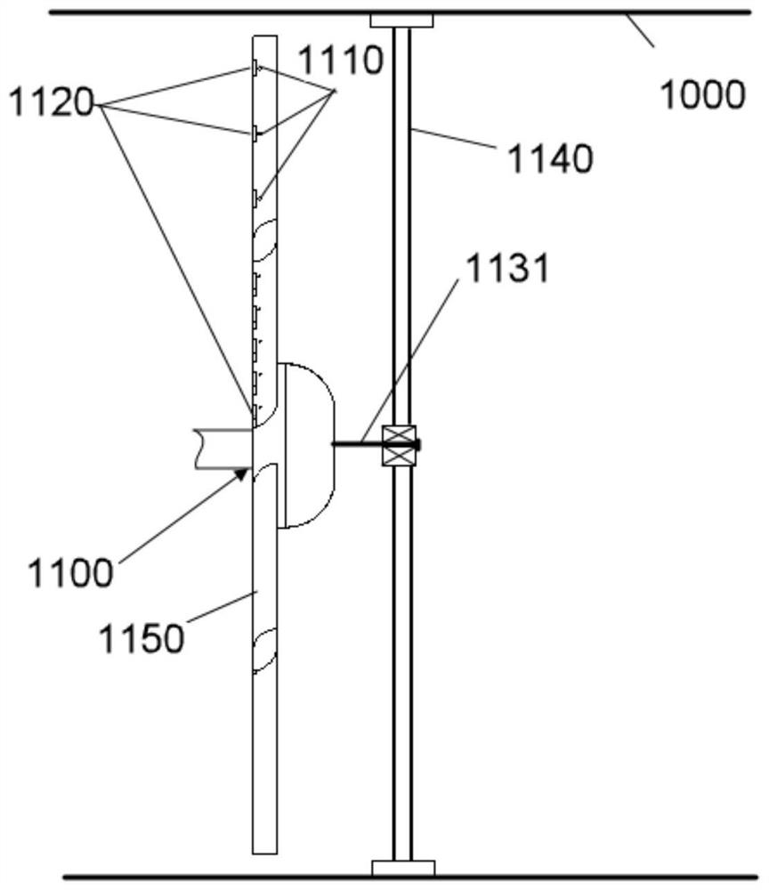
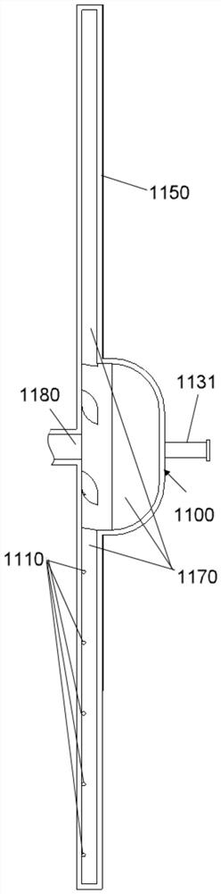
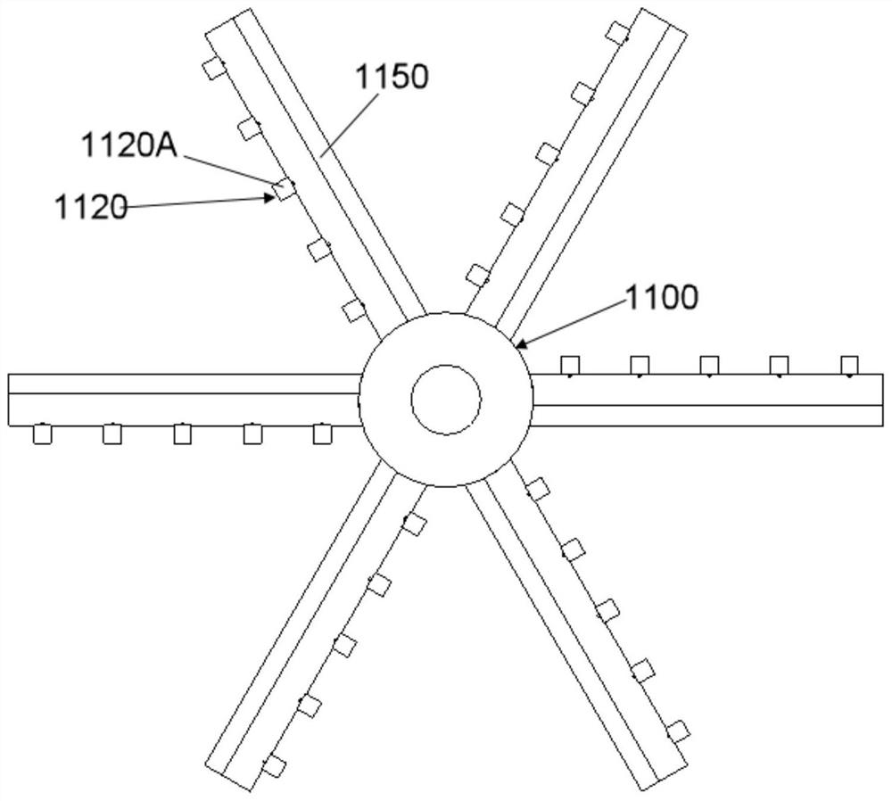
[0051] According to a preferred embodiment, see figure 1 , a distributor 1100, the distributor 1100 is set in the pipeline 1000 in a working state. see figure 2 and 3 , the interior of the dispenser 1100 may be provided with a hollow cavity 1170 for containing liquid medicine. The housing of the dispenser 1100 may be provided with several dispensing holes 1110 for the liquid medicine in the hollow cavity 1170 to flow out. A reflection plate 1120 may be provided adjacent to at least some of the distribution holes 1110 in the plurality of distribution holes 1110 . The corresponding reflective plate 1120 can flow out of the area where the reflective plate 1120 is located under the action of the reflective plate 1120 after at lea...

Embodiment 2

[0070] This embodiment may be a further improvement and / or supplement to Embodiment 1, and repeated content will not be repeated here. In the case of no conflict or contradiction, the whole and / or part of the content of the preferred implementations of other embodiments may serve as supplements to this embodiment.

[0071] According to a preferred embodiment, see Figure 7 , a clarifier 1200, which can be used for pretreatment of high-salt wastewater to remove impurity particles. Preferably, the clarification tank 1200 may include a tank body 1210, at least one water inlet pipe 1220 for transporting the liquid to be treated and a distributor 1100 of the present invention, the distributor 1100 is arranged in the pipeline 1000 of the water inlet pipe 1220, and the distributor 1100 Liquid medicine is housed in it, and the liquid medicine can be coagulant or flocculant. The liquid medicament can be connected to the liquid medicament supply device 1240 through the feed pipe 1230 ...


PUM


Abstract

The invention relates to a distributor and a clarification tank. The distributor is arranged in a pipeline under the working condition. The inside of the distributor is provided with a hollow cavity for accommodating a liquid medicament, and the distributor is provided with several distribution holes used for letting the liquid medicament in the hollow cavity flow out. Baffle boards are arranged adjacent to at least part of the distribution holes, and the baffle boards are arranged according to the following mode: at least a part of the liquid medicament flowing out of the corresponding distribution holes is impacted by the liquid in the pipeline onto the baffle boards and is then reflected towards the place outside the area of the baffle boards under the action of the baffle boards so asto be mixed with the liquid in the pipeline by the utilization of the flowing liquid. By the flowing of the liquid during the pipeline transportation of the liquid, the liquid medicament and the liquid in the pipeline are mixed, and the liquid medicament flowing out of the distribution holes will be impacted by the liquid onto the baffle boards and reflected to the place outside the area of the baffle boards. Thereby, the liquid medicament is quickly dispersed under the reflection effect of the baffle boards, and the mixing effect is improved.

Description

technical field [0001] The invention relates to the field of water treatment, in particular to a distributor and a clarifier. Background technique [0002] With the depletion of clean water resources and the deterioration of the natural water environment, sewage treatment and reuse has become imminent, especially in thermal power plants, petrochemical plants and other large water users, urban reclaimed water has become the first choice for power plant circulating water replenishment water source, as The application of clarifier equipment, which is a necessary link in urban reclaimed water reuse, is even more essential. [0003] At present, the commonly used clarifiers in the field of water treatment include: mechanical acceleration clarifiers, hydraulic circulation clarifiers, suspension clarifiers and pulse clarifiers. [0004] For example, the Chinese patent document whose publication number is CN106477696A discloses a high-efficiency mechanical agitation clarifier. Incl...

Claims


Application Information

Patent Timeline
Patent Type & Authority Patents(China)
IPC IPC(8): B01F5/00C02F9/10
CPCC02F1/22C02F1/42C02F1/442C02F1/444C02F1/4693C02F1/52C02F9/00C02F2001/425C02F2301/08
Inventor 张建飞王志稳赵庆刘丰收
Owner BGT GRP CO LTD
Why Eureka
Try Eureka