Multi-layer turning wheel structure of water turbine

A technology of water turbines and runners, applied in hydropower, mechanical equipment, machines/engines, etc., can solve the problems of difficult manufacturing and transportation, large size of key parts, and high construction costs, so as to reduce the difficulty of manufacturing and transportation and improve the cost of benefits Ratio, the effect of increasing unit capacity

Pending Publication Date: 2019-02-01
浙江富春江水电设备有限公司
View PDF1 Cites 6 Cited by
  • Summary
  • Abstract
  • Description
  • Claims
  • Application Information

AI Technical Summary

Problems solved by technology

The stand-alone capacity of the hydro turbine cannot be effectively broken through, and the power generation benefit is not significant
The key parts used in traditional large-scale turbines are oversized, difficult to manufacture and transport, and the cost cannot be effectively r...

Method used


Image

  • Multi-layer turning wheel structure of water turbine
  • Multi-layer turning wheel structure of water turbine
  • Multi-layer turning wheel structure of water turbine

Examples


Embodiment 1

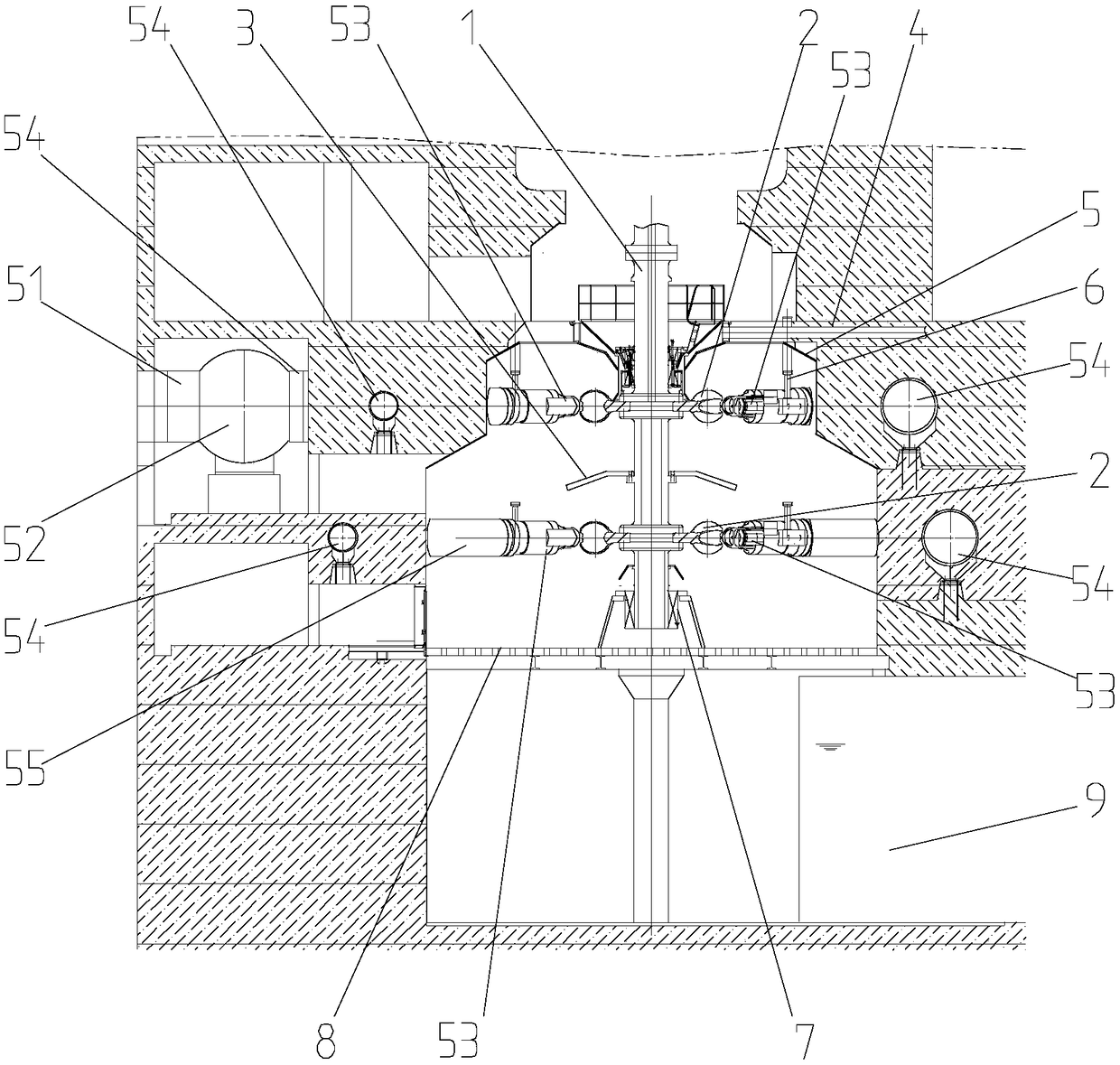
[0021] Such as figure 1 The shown embodiment 1 is a multi-layer runner structure of a water turbine. The multi-layer runner structure of the water turbine in this example is provided with a vertical main shaft 1, the generator is connected above the main shaft, and the lower end is installed in the shaft seat fixed on the maintenance platform. Two upper and lower runners 2 are installed on the main shaft. Two water inlet pipes 51 are arranged up and down to supply water to the two runners respectively.

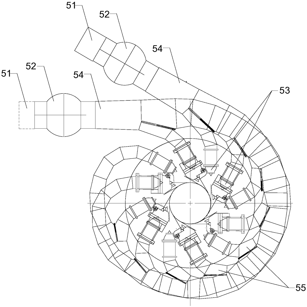
[0022] Such as image 3 , Figure 4 As shown, the upstream open end of the water inlet pipe can be independently connected to the water body of the dam, or connected to the water body of the dam after being merged upstream, a ball valve 52 is installed at the downstream end, and a water distribution pipe 54 is provided at the downstream end of the ball valve, which can independently control each Opening and closing of water distribution pipes. The height of each water dist...

Embodiment 2

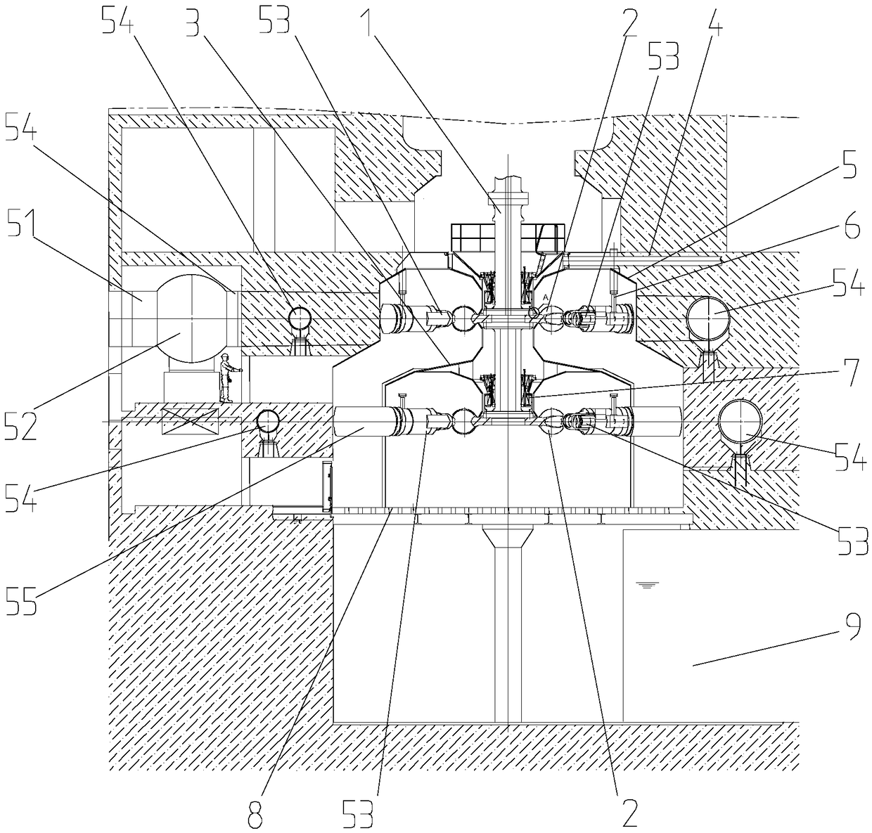
[0027] Such as figure 2 The shown embodiment 2 is another multi-layer runner structure of a water turbine. What the water isolation device selected in this structure is a closed isolation cover, which seals the lower runner and each nozzle. The isolation cover can also be called an inner casing, corresponding to the outer casing.

[0028] The lower end of the main shaft of this example is suspended, and the bearing is installed in the inner casing between the two runners. The bearing can also be arranged on the maintenance platform in the manner of embodiment 1.

[0029] The rest are the same as embodiment 1.


PUM


Abstract

The invention discloses a multi-layer turning wheel structure of a water turbine. The multi-layer turning wheel structure comprises a spindle and at least two water inlet pipes. At least two turning wheels are mounted on the vertical spindle. The downstream end of each water inlet pipe is provided with a ball valve. The lower end of each ball valve is connected with a water distribution pipe. Thedownstream end of each water distribution pipe is provided with a spray nozzle. The spray nozzles are matched with the corresponding turning wheels in position. The at least two turning wheels are arranged on the spindle in an up-down mode. The spray nozzles are matched with the corresponding turning wheels in position. The multi-layer turning wheel structure has the beneficial effects that the water head and flow are utilized to a greater extent, and the unit capacity is substantially increased; moreover, the sizes of key components of the water turbine such as the turning wheels, the water distribution pipes and the ball valves are compressed, and the manufacturing and transportation difficulty is reduced; by adopting smaller unit components, the area of a workshop can be reduced, and the capital construction scale is reduced; more turning wheels provide more spray nozzles, and the radial force of bearings during operation can be reduced; the more spray nozzles provide wider flow regulation capacity, so that the unit keeps operating in a high-efficiency zone, and higher comprehensive benefits are obtained.

Description

technical field [0001] The invention relates to the field of hydropower generation, in particular to a multi-layer runner structure of a water turbine. Background technique [0002] Hydropower generation can convert the potential energy of high-altitude water bodies into electrical energy without any pollution and greenhouse gases generated during the power generation process. It is an important clean energy source. Moreover, water resources have the advantages of being inexhaustible and recyclable, which is in line with the development goals of human society. Chinese patent document CN108105012A disclosed on June 1, 2018 a "water turbine device for generating electricity using the natural flow of river water", including a water turbine and a water guide mechanism. The water turbine includes a runner, an upper shaft and a lower shaft, and the runner includes multiple long blades , a plurality of short vanes and at least two discs arranged at intervals, two adjacent discs ar...

Claims


Application Information

Patent Timeline
IPC IPC(8): F03B1/00F03B1/04
CPCF03B1/00F03B1/04Y02E10/20Y02P70/50
Inventor 沈钊根张续钟熊建军龚芹炬陈璨沈丹任尚洁蒋昭杨希华杨柯马建峰
Owner 浙江富春江水电设备有限公司
Why Eureka
Try Eureka