


Quick Research
Generate reliable direction feasibility study reports for your R&D in just a few steps.

Technical Q&A
Discover and master advanced knowledge NOW. Basics, ideas, possibilities, all at once.

Find Solutions
As an expert in R&D theories, this can generate solutions to your technical problems instantly.

Evaluate Feasibility
Analyze your overall solution with one click, know your potential R&D risks in advance.

Monitor Landscape
Get weekly tech updates, stay abreast of the latest tech innovations and key insights.
H-type finned tube and H-type finned tube heat exchanger
A finned-tube type and finned-tube technology, which is applied in the field of H-shaped finned-tube heat exchangers, can solve the problems of low airflow velocity and reduced heat transfer performance on the leeward side of the H-shaped finned tubes, and achieve local resistance. The effect of small coefficient and high heat transfer performance
- Summary
- Abstract
- Description
- Claims
- Application Information
AI Technical Summary
Problems solved by technology
Method used
Image

Examples
no. 1 example
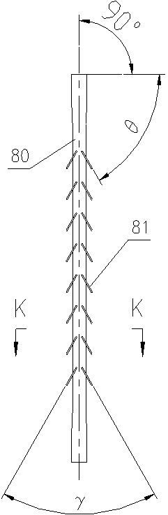
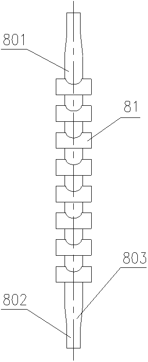
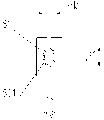
[0043] like Figure 1 ~ Figure 3 As shown, an H-shaped finned tube provided by the present invention includes a base tube 80 and multiple pairs of fins. The base pipe 80 includes a base pipe main body 801 with an elliptical cross section and a base pipe connecting portion 802 located at both ends of the base pipe 80 and having a circular cross section; the base pipe main body 801 is connected to the base pipe connecting portion through a base pipe transition portion 803 802 connected. Each pair of fins includes two straight fins 81 with a symmetrical structure that are symmetrically fixedly connected to the main body 801 of the base pipe; each straight fin 81 in each pair of fins is provided with A groove conforming to the outer wall of the base pipe main body 801, and when the base pipe main body 801 is perpendicular to the horizontal plane, the inner side of each straight fin 81 in each pair of fins is higher than its outer side, so that The dust falling on the straight fi...
no. 2 example
[0053] like Figure 6 ~ Figure 8 As shown, an H-shaped finned tube provided by the present invention includes two base tubes 80' arranged in parallel and multiple pairs of fins. The base pipe 80' includes a base pipe main body 801' with an elliptical cross section and base pipe connecting parts 802' located at both ends of the base pipe 80' and having a circular cross section; the base pipe main body 801' passes through the base pipe transition part 803 ' communicates with the base pipe connection part 802'. Each pair of fins includes two triangular corrugated fins 81' with a symmetrical structure that are symmetrically fixedly connected to the base pipe main body 801' of the two base pipes 80'; The inner side of the corrugated fins 81' is provided with two grooves matching the outer wall of the base pipe main body 801', and when the base pipe main body 801' is perpendicular to the horizontal plane, each piece of triangular corrugation in each pair of fins The inner sides of...
no. 3 example
[0063] like Figure 11 ~ Figure 13 As shown, the first H-shaped finned tube in this embodiment includes two base tubes 80 "and many pairs of fins arranged in parallel. The base tube 80" includes a base tube main body 801" that is elliptical in cross section and is located at The substrate pipe connecting portion 802 ″ at both ends of the substrate pipe 80 ″ is circular in cross section; the substrate pipe main body 801 ″ communicates with the substrate pipe connecting portion 802 ″ through a substrate pipe transition portion 803 ″. Each pair of fins includes two symmetrically fixed sinusoidal corrugated fins 81" fixedly connected to the base pipe main bodies 801" of two base pipes 80"; each pair of fins is sinusoidal The inner side of the corrugated fins 81" are provided with two grooves matching the outer wall of the base pipe main body 801", and when the base pipe main body 801" is perpendicular to the horizontal plane, each pair of fins has sinusoidal corrugations The inne...
PUM
 Abstract
Description
Claims
Application Information
 - R&D Engineer
- R&D Manager
- IP Professional
- Industry Leading Data Capabilities
- Powerful AI technology
- Patent DNA Extraction
Browse by: Latest US Patents, China's latest patents, Technical Efficacy Thesaurus, Application Domain, Technology Topic, Popular Technical Reports.
© 2024 PatSnap. All rights reserved.Legal|Privacy policy|Modern Slavery Act Transparency Statement|Sitemap|About US| Contact US: help@patsnap.com