Heterogeneous emitting electrode structure of solar cell and solar cell

A solar cell and emitter technology, applied in the field of solar cells, can solve problems such as low cell conversion efficiency, and achieve the effects of improving lateral transmission efficiency, improving surface passivation performance, improving filling factor and conversion efficiency

Pending Publication Date: 2019-02-01
TAIZHOU LERRISOLAR TECH CO LTD
View PDF0 Cites 4 Cited by
  • Summary
  • Abstract
  • Description
  • Claims
  • Application Information

AI Technical Summary

Problems solved by technology

[0004] In view of the shortcomings of the existing methods, the present application proposes a heterogeneous emitter structure of solar cells and solar cells to solve the technical problem of low conversion efficiency of the cells in the prior art

Method used


Image

  • Heterogeneous emitting electrode structure of solar cell and solar cell
  • Heterogeneous emitting electrode structure of solar cell and solar cell
  • Heterogeneous emitting electrode structure of solar cell and solar cell

Examples


Embodiment 1

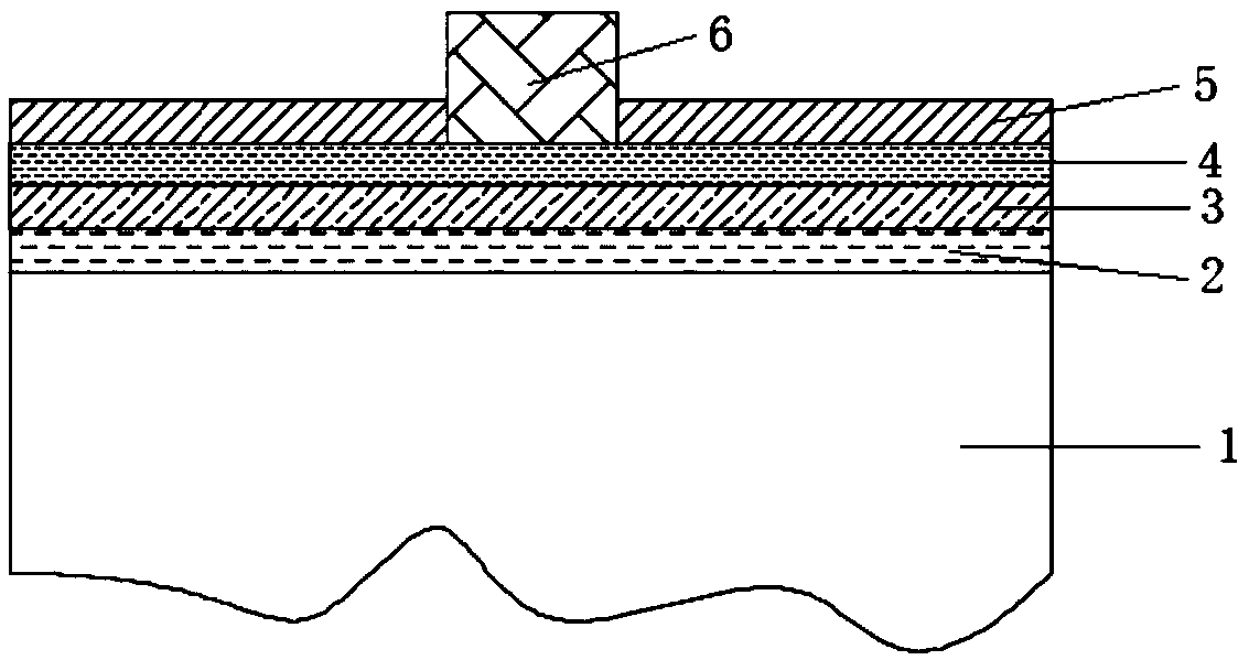
[0041] Embodiment 1 of the present application provides a heterogeneous emitter structure of a solar cell, and the structural schematic diagram of the heterogeneous emitter structure is as follows figure 1 As shown, it includes: a substrate 1, a first doped layer 2, a passivation tunneling layer 3, a second doped layer 4, a passivation anti-reflection layer 5 and a front electrode 6 (negative electrode thin grid line); the substrate 1, The first doped layer 2 , the passivated tunneling layer 3 , the second doped layer 4 and the passivated anti-reflection layer 5 are arranged in sequence, and the front electrode 6 passes through the passivated anti-reflection layer 5 and contacts the second doped layer 4 .

[0042] Compared with the prior art, the embodiment of the present application adds a passivation tunneling layer 3 to provide better passivation, which can effectively reduce the surface recombination rate and provide a good surface passivation for the battery; at the same t...

Embodiment 2

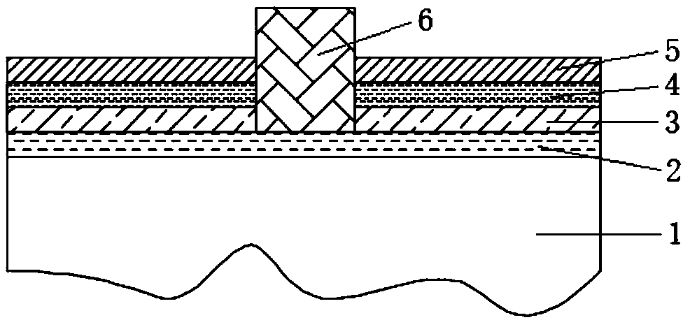
[0059] Based on the same inventive concept, the embodiment of the present application provides another heterogeneous emitter structure of a solar cell. The structural schematic diagram of the heterogeneous emitter structure is as follows figure 2 As shown, it includes: a substrate 1, a first doped layer 2, a passivation tunneling layer 3, a second doped layer 4, a passivation anti-reflection layer 5 and a front electrode 6; a substrate 1, a first doped layer 2, The passivation tunneling layer 3 , the second doped layer 4 and the passivation anti-reflection layer 5 are arranged in sequence, and the front electrode 6 passes through the passivation anti-reflection layer 5 and is in contact with the second doped layer 4 .

[0060] Compared with the prior art, the embodiment of the present application adds a passivation tunneling layer 3 to provide better passivation, which can effectively reduce the surface recombination rate and provide a good surface passivation for the battery;...

Embodiment 3

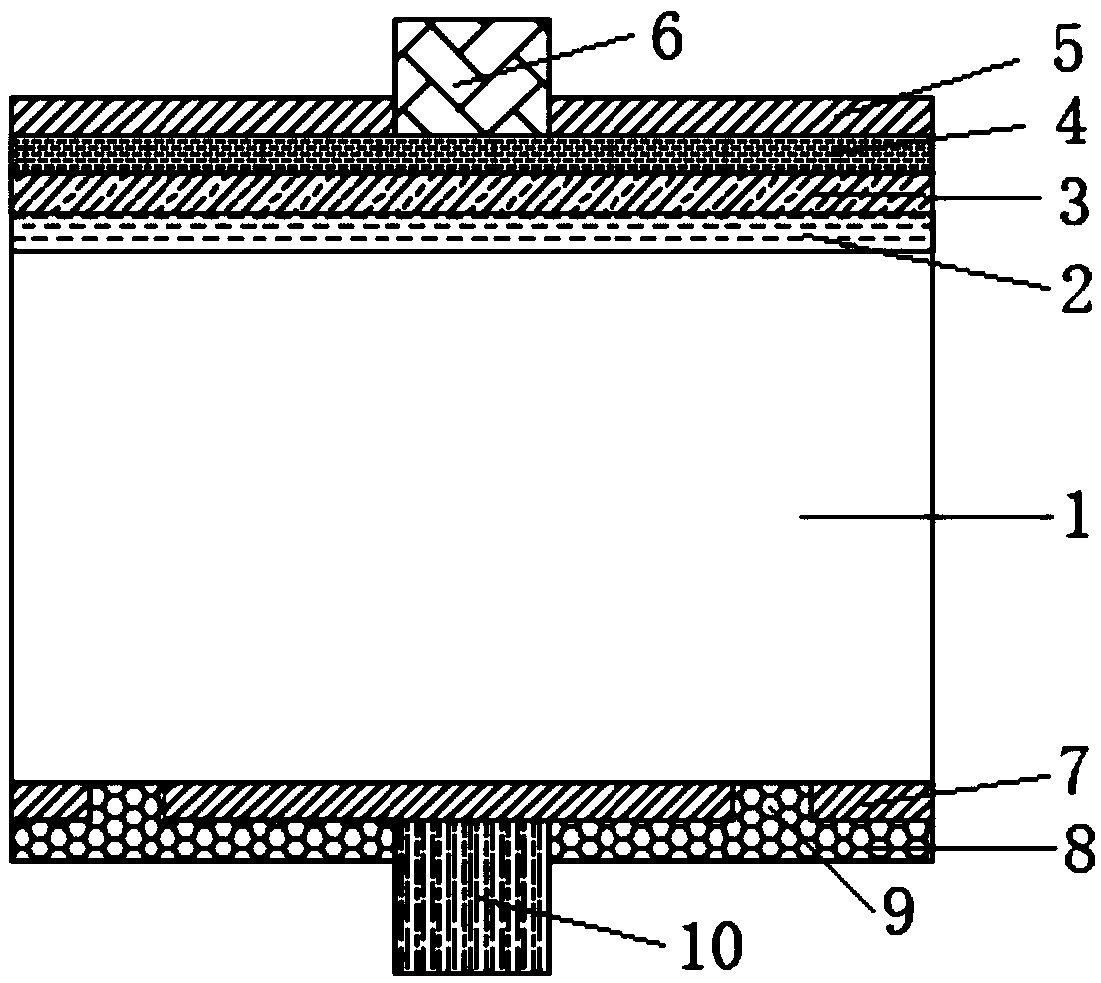
[0078] Based on the same inventive concept, an embodiment of the present application provides a solar cell, and the structural schematic diagram of the solar cell is as follows image 3 , Figure 6 and Figure 7 As shown, it includes: a rear passivation film 7, a rear electrode 8, and any heterogeneous emitter structure of a solar cell as provided in the embodiments of the present application.

[0079] The back passivation film 7 is arranged on the side opposite to the first doped layer 2 of the substrate 1 in the heterogeneous emitter structure; the back electrode 8 is arranged on the side opposite to the substrate 1 of the back passivation film 7; the back electrode 8 The contact region 9 through the rear passivation film 7 (a region that penetrates the rear passivation film 7 and can make contact with structures on both sides of the rear passivation film 7 ) is in contact with the substrate 1 .

[0080] Optionally, the solar cell provided in the embodiment of the present ...


PUM

PropertyMeasurementUnit
Sheet resistanceaaaaaaaaaa
Thicknessaaaaaaaaaa
Thicknessaaaaaaaaaa

Abstract

The present invention provides a heterogeneous emitting electrode structure of a solar cell and a solar cell. The heterogeneous emitting electrode structure of the solar cell comprises a substrate, afirst doping layer, a passivation tunnelling layer, a second doping layer, a passivation antireflection layer and a front electrode. The substrate, the first doping layer, the passivation tunnelling layer, the second doping layer and the passivation antireflection layer are arranged in order, and the front electrode passes through the passivation antireflection layer and is in contact with the second doping layer. In the invention, the passivation tunnelling layer is added to effectively reduce the surface recombination rate of the cell so as to improve the surface passivation performance of the cell; and the front electrode is in contact with the second doping layer to effectively improve the transverse transmission efficiency of the front surface of the cell and reduce the serial resistance of the cell so as to improve the cell filling factor and conversion efficiency and improve the solar cell conversion efficiency.

Description

technical field [0001] The present application relates to the technical field of solar cells, and in particular, the present application relates to a heterogeneous emitter structure of a solar cell and the solar cell. Background technique [0002] At present, with the gradual depletion of fossil energy, solar cells are used more and more widely as a new energy alternative. A solar cell is a device that converts the sun's light energy into electrical energy. Solar cells use the principle of photovoltaics to generate carriers, and then use electrodes to extract the carriers, which is beneficial to the effective use of electrical energy. [0003] The structure of commercial solar cells currently on the market is to prepare a doped layer on the surface of the substrate, and then prepare a passivation layer and electrodes on it. In this case, the doping concentration of the surface doped layer needs to be relatively high, so that the resistivity is relatively low, so that there...

Claims


Application Information

Patent Timeline
IPC IPC(8): H01L31/0224H01L31/04
CPCH01L31/022425H01L31/04Y02E10/50
Inventor 李华童洪波张洪超靳玉鹏
Owner TAIZHOU LERRISOLAR TECH CO LTD
Why Eureka
Try Eureka