Large-scale array antenna and antenna module and antenna unit thereof

An antenna unit and radiating unit technology, applied in directions such as antennas, antenna arrays, and individually powered antenna arrays, can solve problems such as difficulty in meeting low insertion loss, difficulty in realizing lightweight design of the entire antenna system, and increasing the weight of antenna units, etc. Achieve the effect of improving structural reliability and stability, simplifying manufacturing and assembly processes, and ensuring overall structural strength

Inactive Publication Date: 2019-02-01
COMBA TELECOM TECH (GUANGZHOU) CO LTD
View PDF6 Cites 13 Cited by
  • Summary
  • Abstract
  • Description
  • Claims
  • Application Information

AI Technical Summary

Problems solved by technology

Among them, the metal base plate is often formed by metal die-casting or sheet metal process, and the partition is usually formed by metal die-casting, aluminum profile pultrusion or sheet metal process to meet the diverse layout space requirements of antennas based on 5G large-scale dense high-frequency arrays However, such a structure has the following disadvantages in engineering practice: first, the antenna unit is heavy, which makes it difficult to realize the lightweight design of the antenna system; second, the base plate size of the 5G large-scale dense high-frequency array is often large. During the integral molding process of the metal base plate, in order to improve the consistency of the product, the thickness of the metal base plate often needs to be thickened, which will further increase the weight of the antenna unit; the third is that the metal spacer can only be fixed on the metal base plate by screws Or use welding/metal die-casting technology to fix the connection with the metal base plate. On the one hand, in the context of 5G high-frequency band applications, it is difficult to use screw fixing to meet the requirements of 5G high-band antennas for radiation

Method used


Image

  • Large-scale array antenna and antenna module and antenna unit thereof
  • Large-scale array antenna and antenna module and antenna unit thereof
  • Large-scale array antenna and antenna module and antenna unit thereof

Examples


Example Embodiment

[0039] In order to make the technical problems, technical solutions, and beneficial effects to be solved by the present invention clearer, the following further describes the present invention in detail with reference to the accompanying drawings and embodiments. It should be understood that the specific embodiments described herein are only used to explain the present invention, but not to limit the present invention.

[0040] It should be noted that when an element is referred to as being "fixed on" or "installed on" another element, it can be directly on the other element or there may be a centering element at the same time. When an element is said to be "connected" to another element, it can be directly connected to the other element or a central element may be present at the same time.

[0041] In the description of the present invention, it should be understood that the terms “first” and “second” are only used for description purposes, and cannot be understood as indicating o...


PUM

PropertyMeasurementUnit
Thicknessaaaaaaaaaa
Thicknessaaaaaaaaaa

Abstract

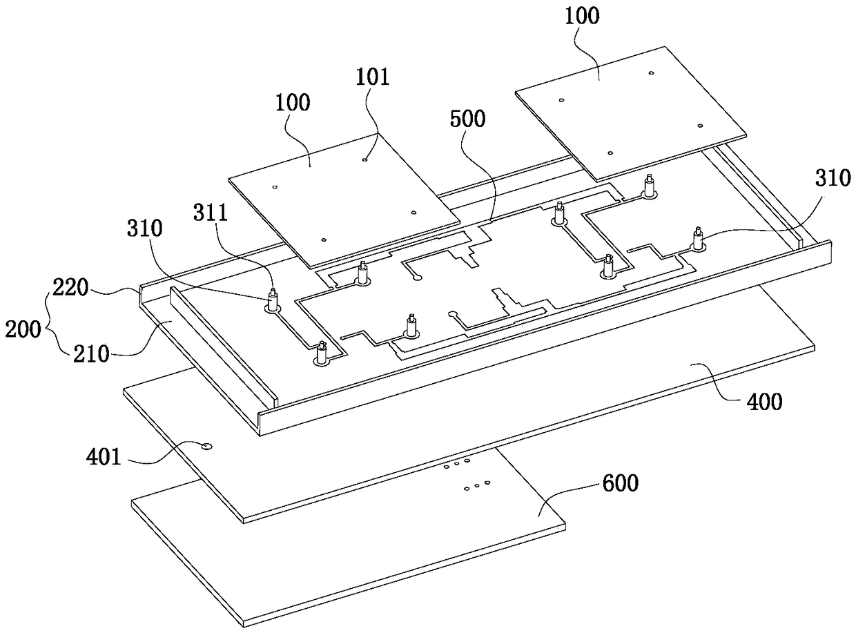
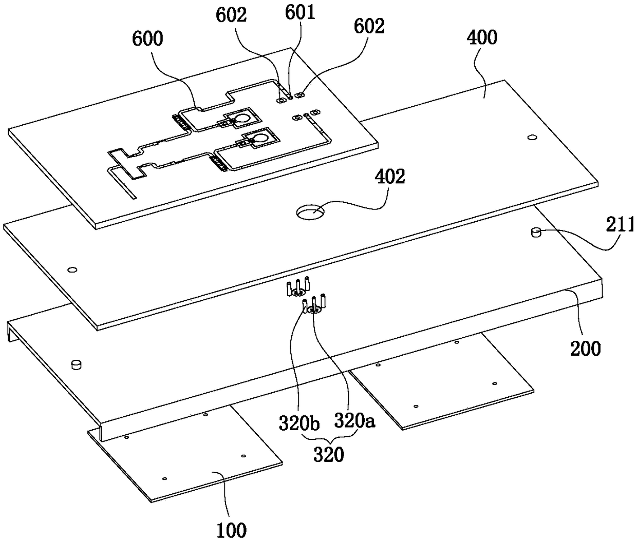
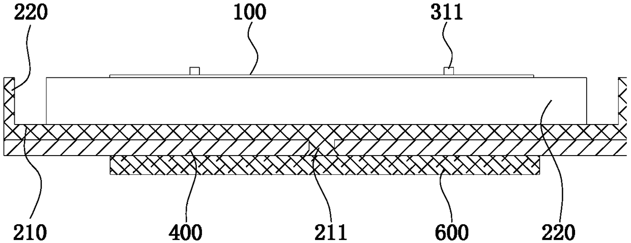
The invention provides an antenna unit, and the antenna unit comprises a radiation unit, an integrally-formed non-metal substrate and a metal reflector, wherein the non-metal substrate comprises a base plate and a separator plate, and the radiation unit and the separator plate are disposed on a top surface of the base plate. The top surface of the base plate is provided with a first metal layer, and the first metal layer is at least partially used to form a feed network circuit layer. At least one side surface of the separator plate is provided with a second metal layer which can enable the separator plate to serve as a radiation boundary, and the metal reflector is disposed on the bottom surface of the base plate. The antenna unit has good structural strength and consistency while achieving light weight and high integration, facilitates the improvement of the electrical performance of the antenna. The present invention also provides an antenna module including the above antenna unit and a large-scale array antenna.

Description

technical field [0001] The invention relates to the technical field of mobile communication, and relates to a large-scale array antenna, an antenna module and an antenna unit thereof. Background technique [0002] With the rapid development of mobile communication technology and applications, the fifth-generation mobile communication technology (abbreviated as 5G in foreign language) has entered the trial commercial stage. [0003] At present, in the 5G antenna solution proposed in the prior art, the antenna unit generally includes a metal base plate and a metal partition disposed on the metal base plate. Among them, the metal base plate is often formed by metal die-casting or sheet metal process, and the partition is usually formed by metal die-casting, aluminum profile pultrusion or sheet metal process to meet the diverse layout space requirements of antennas based on 5G large-scale dense high-frequency arrays However, such a structure has the following disadvantages in e...

Claims


Application Information

Patent Timeline
IPC IPC(8): H01Q19/10H01Q1/50H01Q21/00H01Q21/06
CPCH01Q1/50H01Q19/104H01Q21/0075H01Q21/061
Inventor 段红彬李明超潘荫杰
Owner COMBA TELECOM TECH (GUANGZHOU) CO LTD
Why Eureka
Try Eureka