Synchronous rail driving system and annular production line

A technology of drive system and synchronous track, which is applied in the field of transmission, can solve the problems of low synchronization accuracy and achieve the effect of saving production cost and production cycle

Inactive Publication Date: 2019-02-05
HANS LASER TECH IND GRP CO LTD
View PDF5 Cites 13 Cited by
  • Summary
  • Abstract
  • Description
  • Claims
  • Application Information

AI Technical Summary

Problems solved by technology

[0004] In order to solve the above problems, the present invention provides a synchronous rail drive system and a circul

Method used


Image

  • Synchronous rail driving system and annular production line
  • Synchronous rail driving system and annular production line
  • Synchronous rail driving system and annular production line

Examples


Embodiment 1

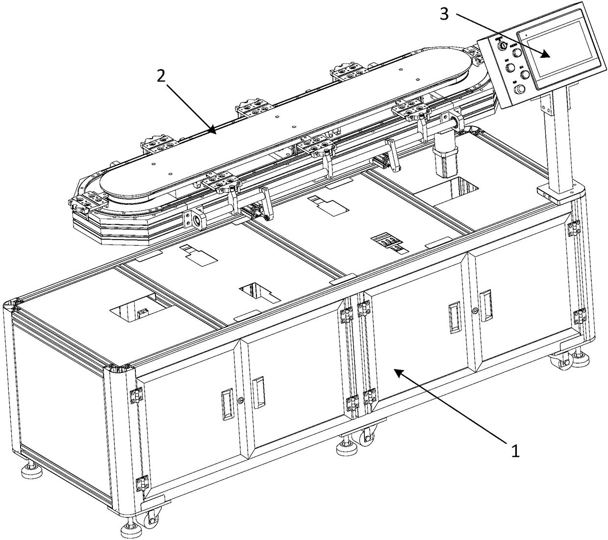
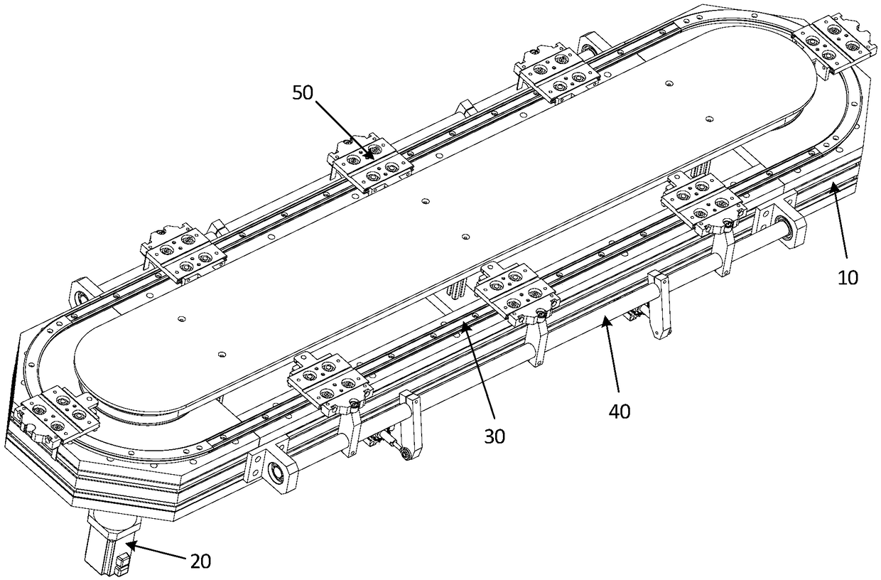
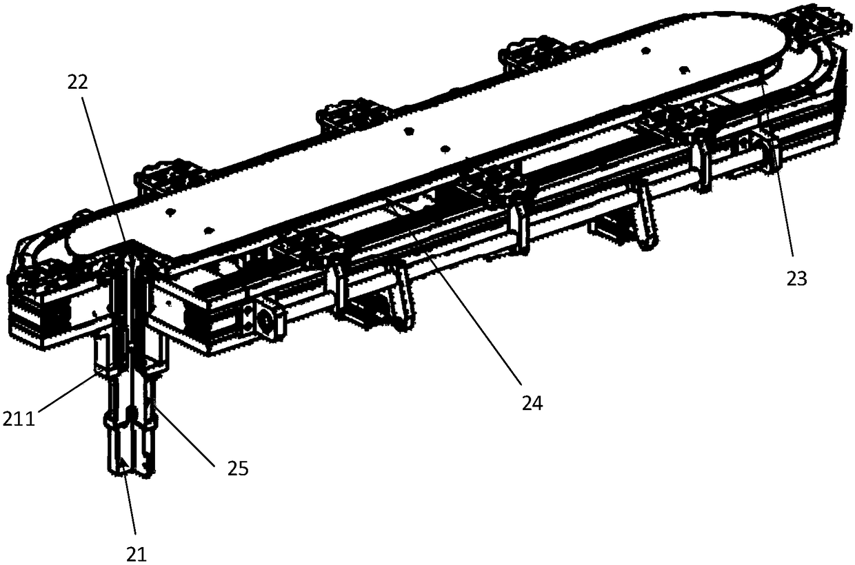
[0035] refer to figure 1 and figure 2 , figure 1 Shown is the overall structure of the synchronous rail drive system provided by the embodiment of the present invention, the synchronous rail drive system includes a cabinet 1 and a table assembly 2, and the table assembly 2 is arranged above the cabinet 1, wherein an engineering control machine is arranged in the cabinet 1 And control bus, the engineering control machine is provided with PLC (Programmable Logic Controller, Programmable Logic Controller), and PLC controls other devices through the control bus; Further, the synchronous track driving system also includes a control panel 3, a control panel 3. Set on the cabinet 1, it can be located at any corner of the cabinet 1. There are multiple control buttons on the control panel 3. Through the control buttons, the synchronous track drive system can be started, shut down, emergency stop, safety lock, etc. At the same time, the system parameters can be set through the visual...

Embodiment 2

[0051] An embodiment of the present invention provides a circular production line. The circular production line includes the synchronous track drive system in the above embodiment. The circular assembly line using the above synchronous track drive system can realize efficient and accurate automatic assembly, and meet the frequent start-up and Stagnation.

[0052] The synchronous track drive system can be combined with multiple manipulators to form a micro-miniature fully integrated automatic production line to realize the output from the input of multiple accessories to the output of finished products. Different assembly equipment can be configured according to needs to meet the diversification of production. For example, in this embodiment, set There are 6 processing stations, see Figure 4 , each processing station corresponds to a slider assembly 50, a fixture is installed on the slider assembly 50, the product is placed on the fixture, and different actions are completed a...


PUM


Abstract

The embodiment of the invention belongs to the technical field of transmission and relates to a synchronous rail driving system and an annular production line. The synchronous rail driving system comprises a cabinet and a table surface assembly. The table surface assembly comprises an annular supporting frame, and a driving device, an annular guide rail, positioning devices and slide block assemblies which are arranged on the annular supporting frame. The annular production line comprises the synchronous rail driving system. According to the synchronous rail driving system, by additionally arranging the positioning devices on the basis of a synchronous belt, the slide block assemblies can be subjected to secondary positioning and locking, accordingly, the purpose of precise positioning isachieved, external equipment can be further effectively connected with the system, different procedure devices are applied to the system simultaneously to form the annular production line, different procedures of workpieces are effectively completed, the production cost is greatly saved, and the production cycle is greatly shortened.

Description

technical field [0001] The embodiment of the invention belongs to the field of transmission technology, and in particular relates to a synchronous track drive system and a circular production line. Background technique [0002] At present, the development trend of automation technology at home and abroad is systematic, flexible, integrated and intelligent. The development of modern production and science and technology puts forward higher and higher requirements for automation technology, and also provides necessary conditions for the innovation of automation technology. The circular automatic assembly line is to achieve efficient and accurate automatic assembly; [0003] The inventor found in the process of realizing the present invention that there are at least the following problems in the prior art: the synchronization accuracy of the existing circular automatic assembly line is low, and if multiple processes are involved, during automatic processing, the synchronizatio...

Claims


Application Information

Patent Timeline
IPC IPC(8): B65G35/06
CPCB65G35/06
Inventor 景俊宁谢祖平刘维波王瑾高云峰
Owner HANS LASER TECH IND GRP CO LTD
Why Eureka
Try Eureka