Device for laser cladding metal surface strengthening and additive manufacturing

A metal surface strengthening and laser cladding technology, which is applied in the direction of additive processing, can solve the problems of reducing work efficiency, reducing production efficiency, and easily causing pollution, etc., and achieves the effect of increasing the practical range, reducing work efficiency, and improving production efficiency

Inactive Publication Date: 2019-02-05
湖北道达智能装备有限公司
View PDF0 Cites 2 Cited by
  • Summary
  • Abstract
  • Description
  • Claims
  • Application Information

AI Technical Summary

Problems solved by technology

Although these traditional repair methods are mature, convenient and quick to implement, and can restore the original geometric dimensions and improve wear resistance, but after repair, the coating is thin, the bonding strength between the coating and the original surface is not high, and it is easy to break down due to local stress concentration. Cracks or peeling of the coating will reduce the effect of strengthening and repairing to a certain extent; moreover, the traditional repairing process also has disadvantages such as easy deformation of the original parts when heated, limited number of cold repairs, and easy pollution.
However, the high value-added metal parts in the petroleum industry are large and valuable parts, and it is difficult to use the above method to ensure their repair quality.
[0003] At present, the laser cladding equipment on the market uses a single cladding head. Considering the precision of the final product, the width of the general cladding head is relatively thin, so the working time is relatively long and the powder outlet device is easy to block; it is impossible to achieve surface strengthening and Remanufacturing is organically combined, which wastes working time and reduces production efficiency; the remanufacturing process is limited by the size of the robot arm and the machine and the space of the device, and the practical scope is limited; the loading and unloading of the powder feeding device basically cannot be fully automated. Either operator assistance is required, or manual loading and unloading operations are required, which reduces work efficiency

Method used


Image

  • Device for laser cladding metal surface strengthening and additive manufacturing

Examples


Embodiment Construction

[0013] The present invention will be further described in detail below in conjunction with the accompanying drawings and specific embodiments.

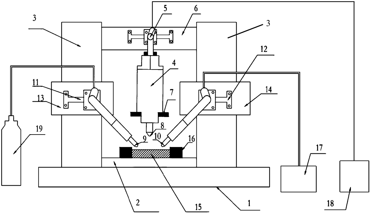
[0014] like figure 1 As shown, a laser cladding metal surface strengthening and additive manufacturing device according to an embodiment of the present invention includes a laser cladding device base plate (1), an XY table (2), a vertical beam (3) and a laser assembly ( 4), six-axis mechanical arm assembly (5), beam (6), laser clamping device (7), laser head emission end (8), inert gas injection port (9), alloy powder outlet (10), fixing bracket (11), fixed bracket (12), support (13), support (14), workpiece (15), workpiece clamping device (16), powder discharge device (17), laser controller (18), inert Gas device (19).

[0015] The first vertical beam (3), the XY-table (2) and the second vertical beam (3) are welded to the laser cladding base plate (1) sequentially by electric welding, and the workpiece (15) passes through the work...


PUM

PropertyMeasurementUnit
thicknessaaaaaaaaaa

Abstract

The invention relates to a device for laser cladding metal surface strengthening and additive manufacturing. A six-axis mechanical arm assembly is coupled to a beam through a hexagon socket bolt, a laser clamping device fixes the laser assembly to the beam, and a laser controller and the laser assembly are connected through an optical fiber. The emitting end of a laser is connected to the clampingdevice, a powder discharging device is connected with an alloy powder outlet through a hose, the alloy powder outlet is fixed to a support through a bracket, and the support is welded to a second vertical beam. An inert gas device is connected to an inert gas injection port through a rubber hose, the inert gas injection port is fixed to the support through the bracket by means of the hexagon socket screw, and the bracket is welded to the first vertical beam. According to the device, various types of powder discharging heads can be replaced according to the demand precision, the power is adjustable, and blockage is not prone to happening; and according to different product requirements, different software programs are designed, laser cladding metal surface strengthening and remanufacturingare organically combined together by adjusting the power and replacing the materials and the powder discharging heads, and the production efficiency is improved.

Description

technical field [0001] The invention relates to the technical field of petroleum equipment, in particular to a device for laser cladding metal surface strengthening and additive manufacturing. Background technique [0002] The repair of high value-added metal parts in the petroleum industry mainly uses technologies such as thermal spraying, brush plating, arc welding and cold surfacing. Although these traditional repair methods are mature, convenient and quick to implement, and can restore the original geometric dimensions and improve wear resistance, but after repair, the coating is thin, the bonding strength between the coating and the original surface is not high, and it is easy to break down due to local stress concentration. Cracks or peeling of the coating will reduce the effect of strengthening and repairing to a certain extent; moreover, the traditional repairing process also has the disadvantages of easy deformation of the original parts when heated, limited number ...

Claims


Application Information

Patent Timeline
Patent Type & Authority Applications(China)
IPC IPC(8): C23C24/10C22C30/00C22C32/00B33Y30/00
CPCC23C24/103B33Y30/00C22C19/07C22C30/00C22C32/0047
Inventor 曹伟刘双程涛张达军曹静远
Owner 湖北道达智能装备有限公司
Why Eureka
Try Eureka