Eureka AIR delivers breakthrough ideas for toughest innovation challenges, trusted by R&D personnel around the world.

Method and system to influence the power generation of an adjustable speed generator

a technology of adjustable speed and generator, which is applied in the direction of electric generator control, machines/engines, mechanical equipment, etc., can solve the problems of difficult to achieve smooth and stable recovery of the system, large space occupation of known dc hopper installations, and high cost, so as to increase the chance of detection

Active Publication Date: 2012-11-06
HITACHI ENERGY SWITZERLAND AG
View PDF8 Cites 16 Cited by
  • Summary
  • Abstract
  • Description
  • Claims
  • Application Information

AI Technical Summary

Benefits of technology

[0009]It is an object of the present invention to provide a method and a system of the kind described above which allow fast influencing of the power generation of the at least one ASG. It is another object of the invention that the system needs lesser space and is less costly than the DC chopper.
[0014]By adjusting the AC voltage in the local AC bus it is possible to provoke an adjustment of the power generated by the at least one ASG. Accordingly, it is no longer necessary to arrange for a DC chopper in the DC link in order to absorb any overpower. Instead an immediate reaction of the power generation of the ASG to changes in the power flow to the AC grid is achieved by controlling the first voltage source converter accordingly. The omittance of the DC chopper leads to a smaller and less costly system.
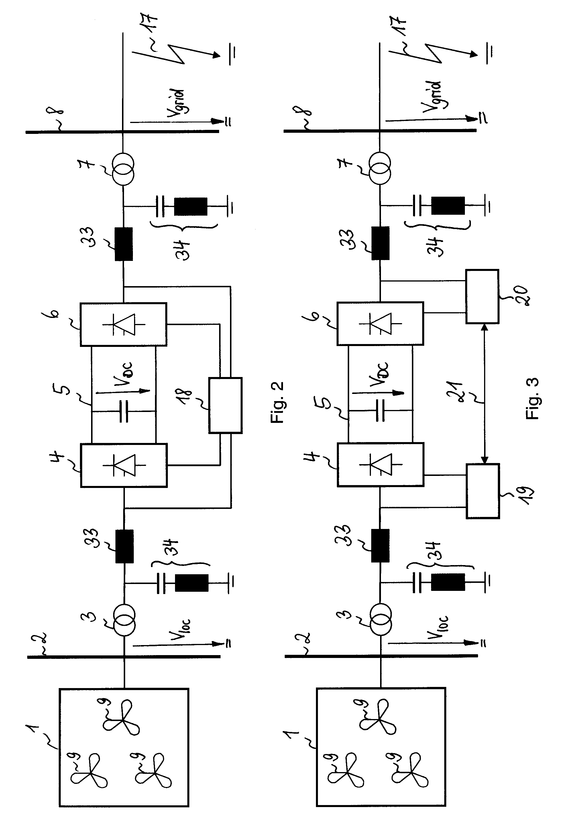
[0015]In an embodiment of the inventive method, a fault in the AC grid is detected, the first voltage source converter is set to control the AC voltage in the local AC bus and the reference value for the AC voltage magnitude is reduced with decreasing AC voltage magnitude of the AC grid. With this method a fast and effective reaction to a fault in the AC grid is achieved, whereby the reduction of the reference value of the AC voltage in the local AC bus leads to a response of the first voltage source converter to reduce the AC voltage magnitude in the local AC bus. This again leads to a reduction in the power generated by the at least one ASG. As a result, overvoltages in the DC link caused by a fault in the AC grid can be prevented. Since no DC chopper is needed, the disturbances of the usual HVDC control can be avoided which results in the possibility for a smooth and stable recovery of the HVDC system after clearance of the fault.
[0016]After clearance of the fault it is suggested according to an extension of the embodiment to increase the reference value for the AC voltage magnitude with increasing AC voltage magnitude of the AC grid. Thereby, the power generation of the at least one ASG can be increased in correlation with the recovery of the AC grid in a smooth and continuous manner.
[0018]Additionally to the rate of the DC voltage, the absolute magnitude level of the DC voltage can be monitored. If the DC voltage rate as well as the DC voltage magnitude each exceeds a predetermined value, a fault in the AC grid is indicated. By monitoring the DC voltage magnitude it is ensured, that the power of the at least one ASG is only adjusted in cases where considerable overpower is detected. Variations in the DC voltage with minor amplitudes are ignored, even if they occur with considerable rate of change, thereby keeping the HVDC system under stable operating conditions as long as possible.
[0019]In a special embodiment of the system, the system comprises a first control unit to control the first voltage source converter and a second control unit to control the second voltage source converter, instead of controlling both voltage source converters via one control unit. According to this embodiment, the second control unit sends the AC voltage magnitude of the AC grid via telecommunication to the first control unit. Since telecommunication usually causes a delay in providing information, the fault detecting method based on the monitoring of the DC voltage rate of change and magnitude could be applied in order to increase the chances to detect a fault in the AC grid even before the voltage information from the AC grid reaches the first control unit.

Problems solved by technology

However, this is not the case for an ASG.
One or a multiple of ASGs connected via a HVDC system with VSCs to an AC grid may encounter the following problem.
The known DC chopper installations require considerable space and are costly.
In addition, the DC chopper control function causes disturbances in the usual HVDC control which make it difficult to achieve a smooth and stable recovery of the system after the fault in the AC grid is cleared.

Method used


Image

  • Method and system to influence the power generation of an adjustable speed generator
  • Method and system to influence the power generation of an adjustable speed generator
  • Method and system to influence the power generation of an adjustable speed generator

Examples


Embodiment Construction

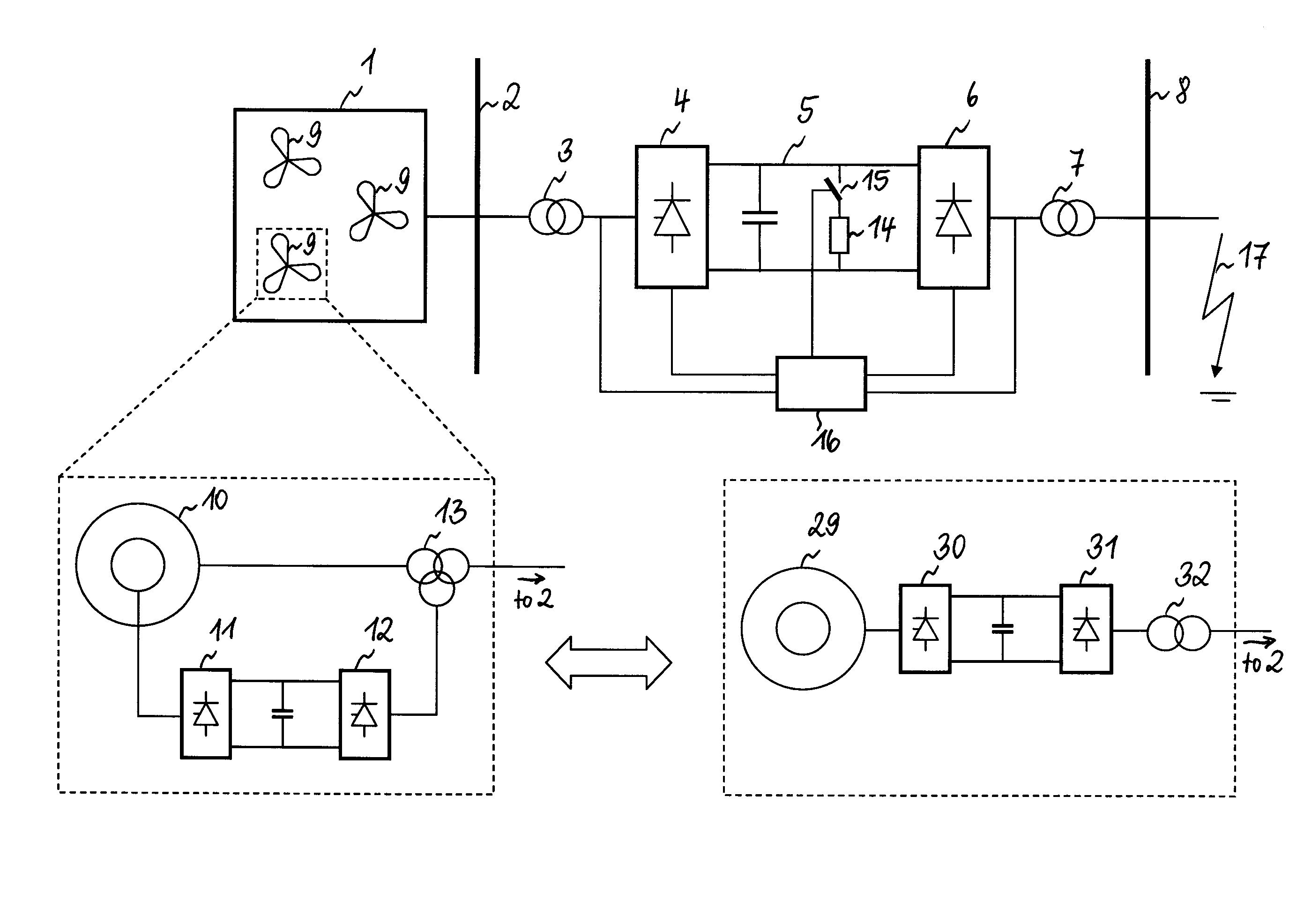
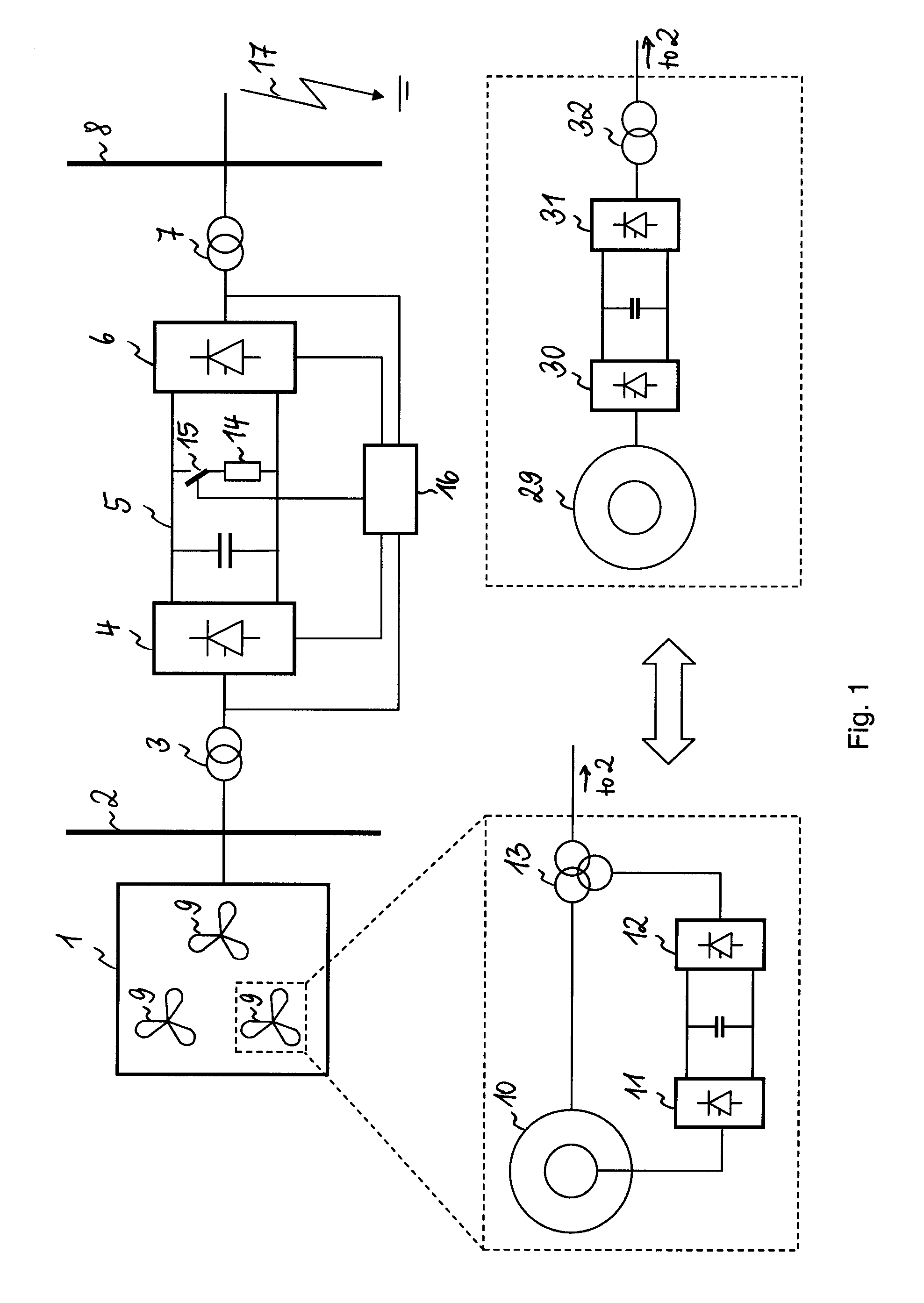
[0025]FIG. 1 shows a schematic diagram of a wind farm 1 and its connection to an AC grid 8, as it is known in the art. The wind farm 1 is coupled to a local AC bus, the local AC bus 2 being connected via a first transformer 3 and / or a reactor (not shown) to a first voltage source converter (VSC) 4. The first VSC 4 is connected via a DC link 5 to a second VSC 6 and the second VSC 6 is connected via a second transformer 7 to an AC grid 8. The wind farm 1 comprises several adjustable speed generators (ASG) 9 which are composed of either a doubly-fed induction generator 10 and two back-to-back connected VSCs 11 and 12 or a synchronous generator 29 with two full-sized converters 30 and 31. The two VSCs 11 and 12 are connected on one side to the rotor of the induction generator 10 and on the other side, via a transformer 13, to the local AC bus 2. The two VSCs 30 and 31 connect the stator of the synchronous generator 29 via a transformer 32 to the local AC bus 2.

[0026]Since the ASGs 9 of ...


PUM


Abstract

A method and a system to influence the power generation of at least one adjustable speed generator. The system includes a first voltage source converter connected to a local AC bus. The local AC bus is provided with power by the at least one adjustable speed generator. A second voltage source converter connected to an AC grid. A DC link is connected between the first and the second voltage source converter. At least one control unit controls the first and the second voltage source converters. The at least one control unit performs the method to control the AC voltage in the local AC bus via the first voltage source converter and to modify a reference value for the AC voltage magnitude of the local AC bus in dependence on the AC voltage magnitude of the AC grid.

Description

CROSS-REFERENCE TO RELATED APPLICATIONS[0001]This application is the national phase under 35 U.S.C. §371 of PCT / EP2007 / 054196 filed 27 Apr. 2007FIELD OF THE INVENTION[0002]The invention relates to a method to influence the power generation of an adjustable speed generator and to a related system, where the system comprises a first voltage source converter connected to a local AC bus, the local AC bus being provided with power by the at least one adjustable speed generator, a second voltage source converter connected to an AC grid, a DC link connected between the first and the second voltage source converter and at least one control unit to control the first and the second voltage source converters.BACKGROUND OF THE INVENTION[0003]Direct current (DC) power transmission systems are used today to interconnect alternating current (AC) power systems and to transmit power at high voltages over long distances. These systems are known in the art as High Voltage Direct Current (HVDC) transmi...

Claims


Application Information

Patent Timeline
Patent Type & Authority Patents(United States)
IPC IPC(8): H02J3/36H02P9/04F03D9/00
CPCH02M5/4505H02J3/386Y02E10/725Y02E10/763H02J2300/28H02J3/381Y02E10/72Y02E10/76H02J3/46
Inventor JIANG-HAFNER, YING
Owner HITACHI ENERGY SWITZERLAND AG
Why Eureka
Eureka Blog
Learn More