Charging device and method for charging an electrical energy store

a charging device and electrical energy technology, applied in the field can solve the problems of reducing the life of electrically isolating converters generally used with electromagnetic transmission elements, unable to achieve optimal design, and unable to achieve the effect of reducing the complexity of controlling the charging of electrical energy stores, reducing the cost, and improving reliability

Inactive Publication Date: 2014-04-17
ROBERT BOSCH GMBH
View PDF7 Cites 17 Cited by
  • Summary
  • Abstract
  • Description
  • Claims
  • Application Information

AI Technical Summary

Benefits of technology

[0011]As a result of the present invention, the control complexity involved in the charging of the electrical energy store can be reduced and, at the same time, the DC voltage converter and thus the entire charging device can be adapted and dimensioned better. Owing to the small dimensions of the capacitors between the rectifier stage and the DC voltage converter, capacitors which are less expensive and more reliable can be used, as a result of which the charging device is overall more reliable and less expensive. Overall, the charging device is therefore technically less complex and less expensive.
[0012]In other words, the voltage at the output voltage connections is determined by the electrical energy store connected, with the result that the output power can be adjusted via the output current. If the voltage between the intermediate circuit connections increases, the voltage difference between the input side and the output side of the DC voltage converter circuit increases, with the result that the current and therefore also the transmitted power increases. As a result, by adjusting the magnitude of the intermediate circuit voltage, the power transmitted to the electrical energy store can be adjusted. As a result, therefore, the transmitted charging power can be adjusted simply by regulating the intermediate circuit voltage.

Problems solved by technology

Electrolyte capacitors demonstrate severe ageing phenomena, however, depending on their current loading and their operating temperature.
For use in the automotive sector, such electrolyte capacitors tend to be usable only to a limited extent as a result of the large specified temperature range and the thus reduced life.
Since the DC voltage converter therefore does not have a constant voltage transformation ratio, the electrically isolating converters generally used with an electromagnetic transmission element cannot have an optimum design.
The electrically isolating soft-switching DC voltage converters used at present lose their soft-switching property above a specific transmission power, with the result that the efficiency is reduced by switching losses additionally occurring.
Disadvantages with the known charging devices therefore include the limited life, the high technical complexity, in particular the high control complexity for adjusting the charging voltage, and the high costs associated therewith.

Method used


Image

  • Charging device and method for charging an electrical energy store
  • Charging device and method for charging an electrical energy store
  • Charging device and method for charging an electrical energy store

Examples


Embodiment Construction

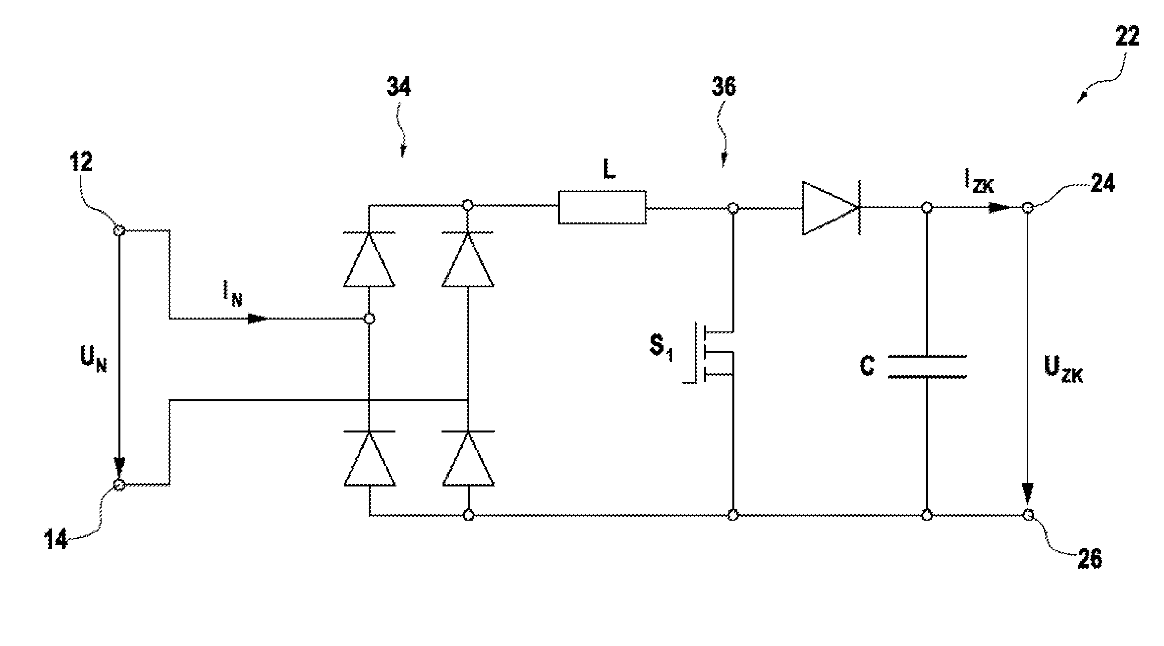
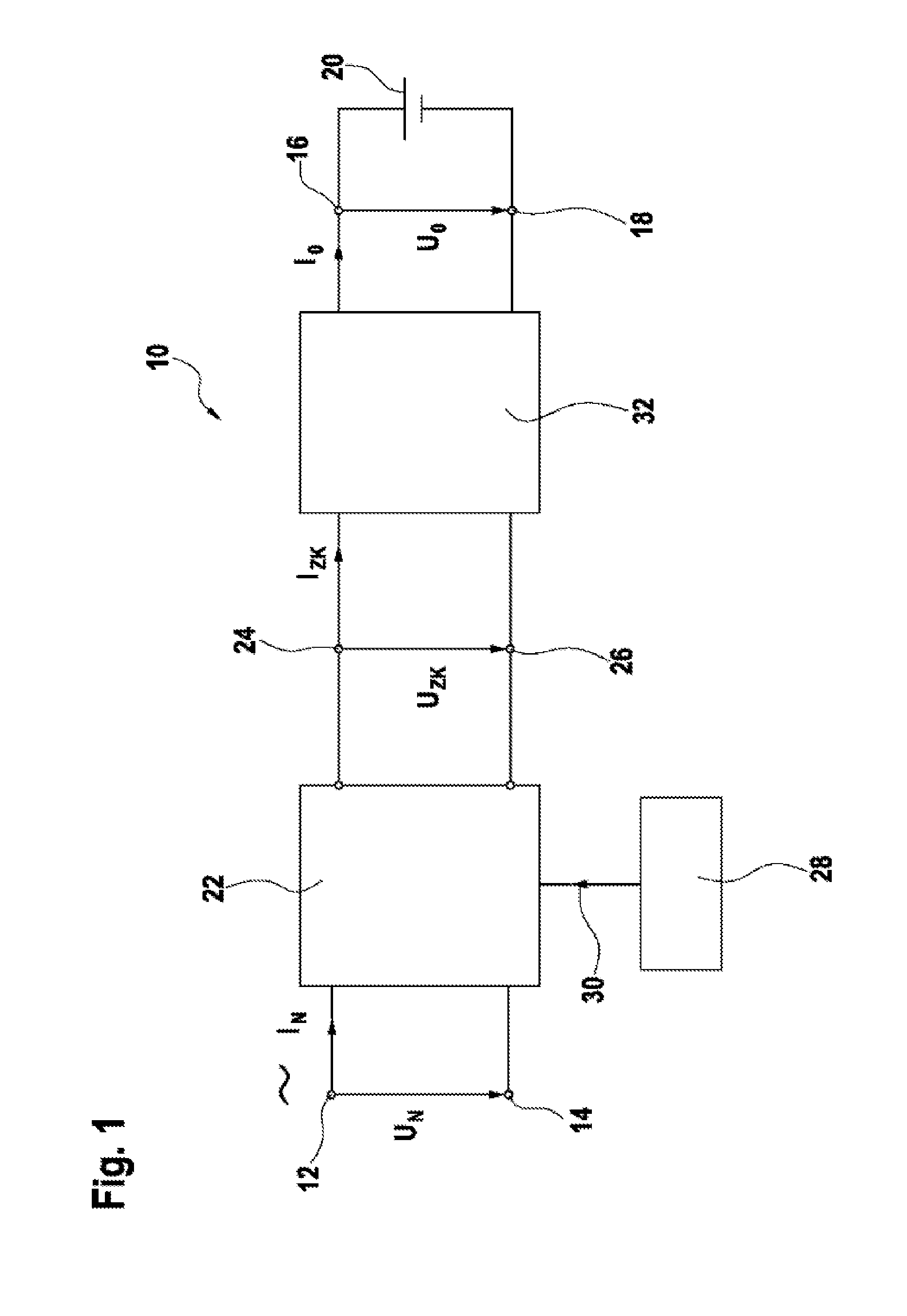
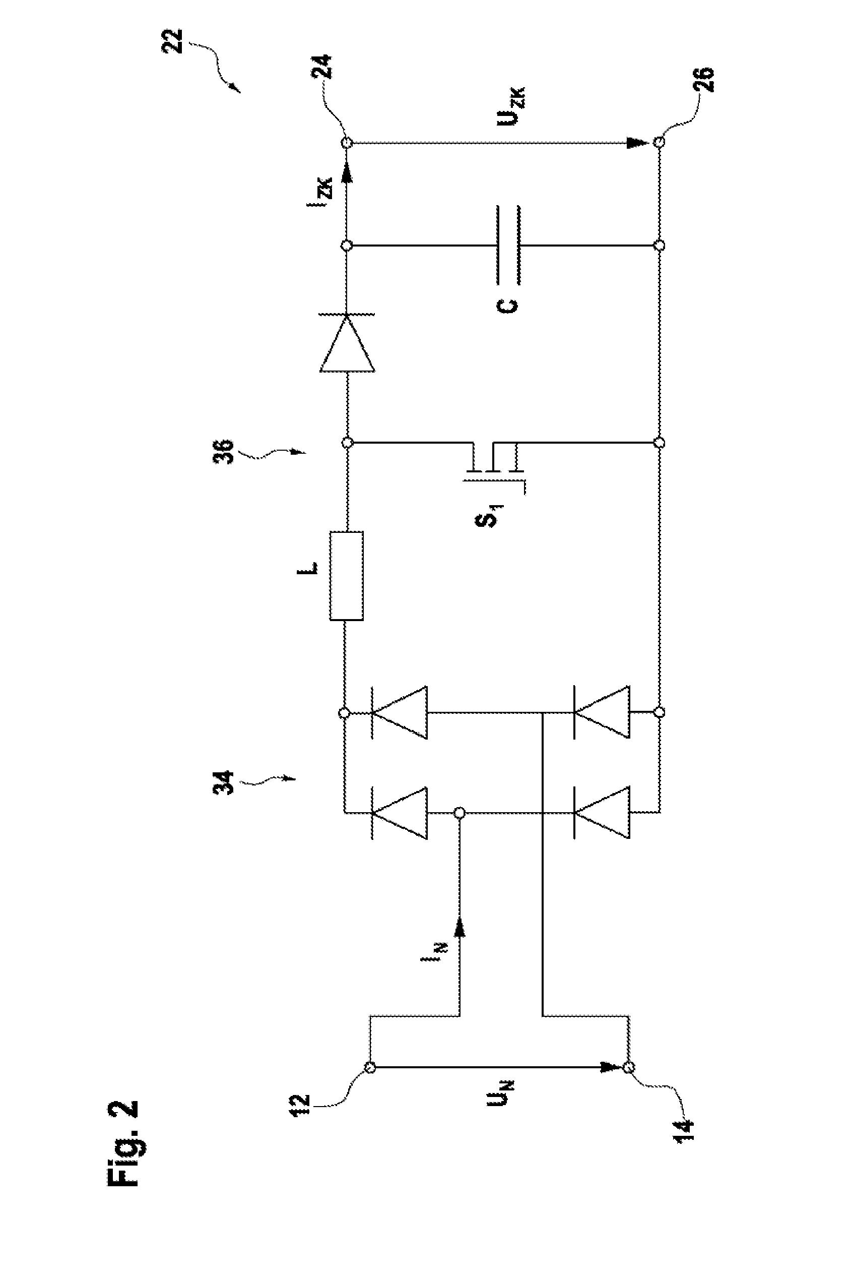
[0034]FIG. 1 shows schematically the circuit of a charging device according to the invention, which is generally denoted by 10.

[0035]The charging device 10 has a first input voltage terminal 12 and a second input voltage terminal 14, which together form a voltage input. In addition, the charging device 10 has a first output voltage terminal 12 and a second output voltage terminal 14, which together form a voltage output. The input voltage terminals 12, 14 are designed to be connected to an AC voltage source (not illustrated). The input voltage UN which preferably corresponds to the public grid voltage is present between the input voltage terminals 12, 14. That is to say that the AC voltage source in a preferred embodiment of the invention is a low-voltage public grid. The charging device 10 provides an input current IN across the input voltage terminals 12, 14. The input voltage UN is an AC voltage and the input current IN is an alternating current, which AC voltage and alternating ...


PUM


Abstract

The present invention relates to a charging device (10) for charging an electrical energy store (20), comprising a first and a second input voltage terminal (12, 14), for connecting the charging device (10) to an AC voltage source, a first and a second output voltage terminal (16, 18) for connecting the charging device (10) to the energy store (20) to be charged, a rectifier voltage converter circuit (22), which on the input side is connected to the input voltage terminals (12, 14) and on the output side is connected to a first and a second intermediate circuit voltage terminal (24, 26) and is designed to provide an intermediate circuit DC voltage (UZK) between the intermediate circuit voltage terminals (24, 26), a DC voltage converter circuit (32) which on the input side is connected to the intermediate circuit terminals (24, 26) and on the output side is connected to the output voltage terminals (16, 18) of the charging device (10), wherein the DC voltage converter circuit (32) is designed to provide a DC output voltage (UO) and a DC output current (10) at the output terminals (16, 18), wherein the intermediate circuit DC voltage (UZK) can be set by means of the rectifier voltage converter circuit (22) in order to set an electrical power (P) that is transmitted from the input voltage terminals (12, 14) to the output voltage terminals (16, 18) or the energy store (20) to be charged.

Description

[0001]The present invention relates to a charging device for charging an electrical energy store comprising a first and a second input voltage connection for connecting the charging device to an AC voltage source, a first and a second output voltage connection for connecting the charging device to the energy store to be charged, a rectifier voltage converter circuit, which is connected on the input side to the input voltage connections and is connected on the output side to a first and a second intermediate circuit voltage connection and is designed to provide a DC intermediate circuit voltage between the intermediate circuit voltage connections, a DC voltage converter circuit, which is connected on the input side to the intermediate circuit connections and is connected on the output side to the output voltage connections of the charging device, wherein the DC voltage converter circuit is designed to provide a DC output voltage and a direct output current at the output connections.[...

Claims


Application Information

Patent Timeline
Patent Type & Authority Applications(United States)
IPC IPC(8): H02J7/02
CPCH02J7/022H02M1/4225H02M3/3376H02M7/217H02J7/02H02J2207/20Y02B70/10Y02B40/00H02M1/007
Inventor FASSNACHT, JOCHENVAN BOOVEN, CHRISTOPH
Owner ROBERT BOSCH GMBH
Why Eureka
Try Eureka