Electroplating unit capable of conveniently adjusting liquid level of electroplating water tank

A technology of electroplating unit and tank liquid, applied in the direction of plating tank, electrolysis process, electrolysis components, etc., can solve the problems of manual operation delay and error, unable to fill the electroplating solution, etc., and achieve the effect of avoiding manual operation

Active Publication Date: 2019-02-05
湖州金业表面科技有限公司
View PDF4 Cites 2 Cited by
  • Summary
  • Abstract
  • Description
  • Claims
  • Application Information

AI Technical Summary

Problems solved by technology

[0003] In the process of continuously filling the electroplating tank with the electroplating solution, the electroplating solution will overflow from the tank. In order to ensure that the electroplating tank contains an appropriate amount of electroplating solution, it is necessary to fill the electroplating tank with the electroplating solution in time during the electroplating process to ensure Realize the adjustment of the liquid level of the electroplating solution. In the prior art, the filling of the electroplating solution is mostly performed through manual observation, and then the operation is performed. Manual operations often have delays and errors, so timely filling of the electroplating solution cannot be realized.

Method used


Image

  • Electroplating unit capable of conveniently adjusting liquid level of electroplating water tank
  • Electroplating unit capable of conveniently adjusting liquid level of electroplating water tank
  • Electroplating unit capable of conveniently adjusting liquid level of electroplating water tank

Examples


Embodiment 1

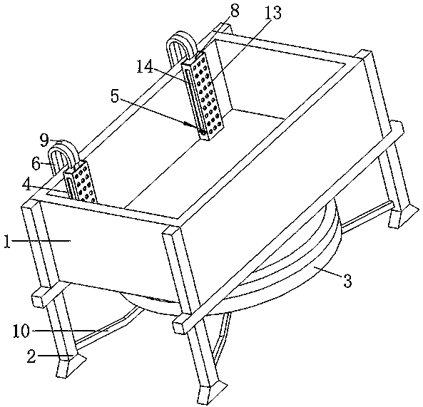
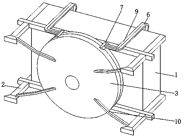
[0038] refer to figure 1 , figure 2 , Figure 4 , an electroplating unit that is convenient for adjusting the liquid level of an electroplating water tank, comprising an electroplating water tank 1, symmetrical legs 2 are fixedly connected to the four corners of the bottom of the electroplating water tank 1, an electroplating solution storage tank 3 is provided at the bottom of the electroplating water tank 1, and the electroplating water tank 1 The inner wall is fixedly connected with a liquid level tube 4, and the floating plate 5 is slidably connected to the liquid level tube 4. The outer wall of the electroplating water tank 1 is fixedly connected with a serpentine sleeve 6, and the top of the serpentine sleeve 6 is placed on the bottom of the liquid level tube 4. Above, the bottom end of the serpentine casing 6 extends downward and is connected to the electroplating solution storage tank 3 through the fixed block 7, and the floating plate 5 is connected to the serpentin...

Embodiment 2

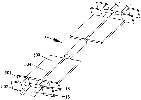
[0041] refer to figure 1 , figure 2 , Figure 4 , Figure 5 , an electroplating unit that is convenient to adjust the liquid level of the electroplating water tank, which is basically the same as that of Embodiment 1, furthermore, a water pump 11 is provided in the filling pipe 9, and a water pipe 12 is connected to the water outlet end of the water pump 11, and the water pipe 12 is far away from the water pump 11 One end of the pipe extends to the top of the filling pipe 9. The existence of the water pump 11 is beneficial to absorb the electroplating solution entering the filling pipe 9 into the water pipe 12, and discharge it into the liquid level pipe 4 through the water pipe 12, so as to realize the electroplating solution. Liquid filling.

Embodiment 3

[0043] refer to Figure 1-8 , an electroplating unit that is convenient for adjusting the liquid level of an electroplating water tank, comprising an electroplating water tank 1, symmetrical legs 2 are fixedly connected to the four corners of the bottom of the electroplating water tank 1, an electroplating solution storage tank 3 is provided at the bottom of the electroplating water tank 1, and the electroplating water tank 1 The inner wall is fixedly connected with a liquid level tube 4, and the floating plate 5 is slidably connected to the liquid level tube 4. The outer wall of the electroplating water tank 1 is fixedly connected with a serpentine sleeve 6, and the top of the serpentine sleeve 6 is placed on the bottom of the liquid level tube 4. Above, the bottom end of the serpentine casing 6 extends downward and is connected to the electroplating solution storage tank 3 through the fixed block 7, and the floating plate 5 is connected to the serpentine casing 6 through the ...


PUM


Abstract

The invention discloses an electroplating unit capable of conveniently adjusting the liquid level of an electroplating water tank, and belongs to the technical field of electroplating machining. The electroplating unit capable of conveniently adjusting the liquid level of the electroplating water tank comprises the electroplating water tank, symmetrical supporting legs are fixedly connected with the four corners of the bottom of the electroplating water groove, an electroplating liquid storage box is arranged at the bottom of the electroplating water tank, a liquid level pipe is fixedly connected with the inner wall of the electroplating water tank, a floating plate is in sliding connection with the liquid level pipe, an S-shaped sleeve pipe is fixedly connected with the outer wall of theelectroplating water tank, the top end of the S-shaped sleeve pipe is arranged above the liquid level pipe, the bottom end of the S-shaped sleeve pipe is extended downwards and is connected with the electroplating liquid storage box through a fixing block, the floating plate is connected with the S-shaped sleeve pipe through a traction rope, and the traction rope sequentially penetrates through the S-shaped sleeve pipe and the fixing block and extends into the electroplating liquid storage box. Operation is convenient, the operation that electroplating liquid is added through manual observation is abandoned, defects of manual operation are avoided, and automatic adding of the electroplating liquid is achieved.

Description

technical field [0001] The invention relates to the technical field of electroplating processing, in particular to an electroplating unit which is convenient for adjusting the liquid level of an electroplating tank. Background technique [0002] Electroplating refers to the technology of using the principle of electroplating pool to deposit a metal coating with good adhesion but different properties from the base material on mechanical products. The electroplating layer is more uniform than the hot-dip layer and is generally thinner, ranging from a few microns to tens of The micron ranges. Through electroplating, decorative protective and various functional surface layers can be obtained on mechanical products, and workpieces with wear and processing errors can also be repaired; the purpose of electroplating is to coat the substrate with a metal coating to change the substrate. Surface properties or dimensions, electroplating can enhance the corrosion resistance of metals, e...

Claims


Application Information

Patent Timeline
Patent Type & Authority Applications(China)
IPC IPC(8): C25D17/04C25D17/00C25D17/02
CPCC25D17/00C25D17/02C25D17/04
Inventor 金建忠徐永江杨新明李立新邱银泉
Owner 湖州金业表面科技有限公司
Why Eureka
Try Eureka