Automatic flow control system for stationary type foundry furnace

A casting furnace and stationary technology, applied in casting equipment, control of pouring molten metal from ladle, manufacturing tools, etc. Easy installation, reduced slag formation, and strong practical functions

Inactive Publication Date: 2019-02-12
SUZHOU ZHONGYANG THERMAL ENERGY TECH CO LTD
View PDF0 Cites 3 Cited by
  • Summary
  • Abstract
  • Description
  • Claims
  • Application Information

AI Technical Summary

Problems solved by technology

[0003] At present, the drill bit assembly for flow control of the fixed furnace is basically manually controlled, requiring the operator to continuously adjust the position of the drill bit assembly. The labor intensity is high, and the discharge control accuracy is poor, which will cause fluctuations in the level of the casting liquid, which will affect the casting process and the final product quality. Both bring adverse effects. Although the tilting casting furnace can solve the problem of casting liquid level fluctuations, the tilting casting furnace has a huge investment and is not suitable for the production process requirements of all alloy products. Therefore, the fixed furnace casting furnace is still the current choice. Aluminum Alloy Mainstream Casting Production Furnace
[0004] In the past few years, various types of automatic flow control devices have been studied in the industry, but generally speaking, they are all simple drill bit assembly controls, and the research on complex working conditions is insufficient, and the operation convenience is not enough. Therefore, they have not been obtained. Promote application

Method used


Image

  • Automatic flow control system for stationary type foundry furnace
  • Automatic flow control system for stationary type foundry furnace
  • Automatic flow control system for stationary type foundry furnace

Examples


Embodiment Construction

[0021] It should be noted that when an element is referred to as being "fixed to" another element, it can be directly on the other element or intervening elements may also be present. When an element is referred to as being "connected" to another element, it can be directly connected to the other element or intervening elements may also be present.

[0022] Unless otherwise defined, all technical and scientific terms used herein have the same meaning as commonly understood by one of ordinary skill in the art to which this invention belongs. The terms used herein in the description of the present invention are for the purpose of describing specific embodiments only, and are not intended to limit the present invention. As used herein, the term "and / or" includes any and all combinations of one or more of the associated listed items.

[0023] In order to make the purposes, technical solutions and advantages of the embodiments of the present invention clearer, the technical soluti...


PUM


Abstract

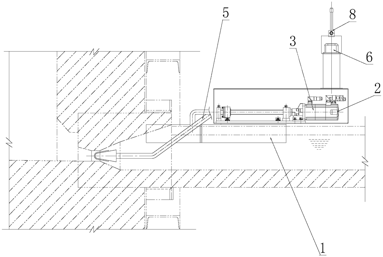
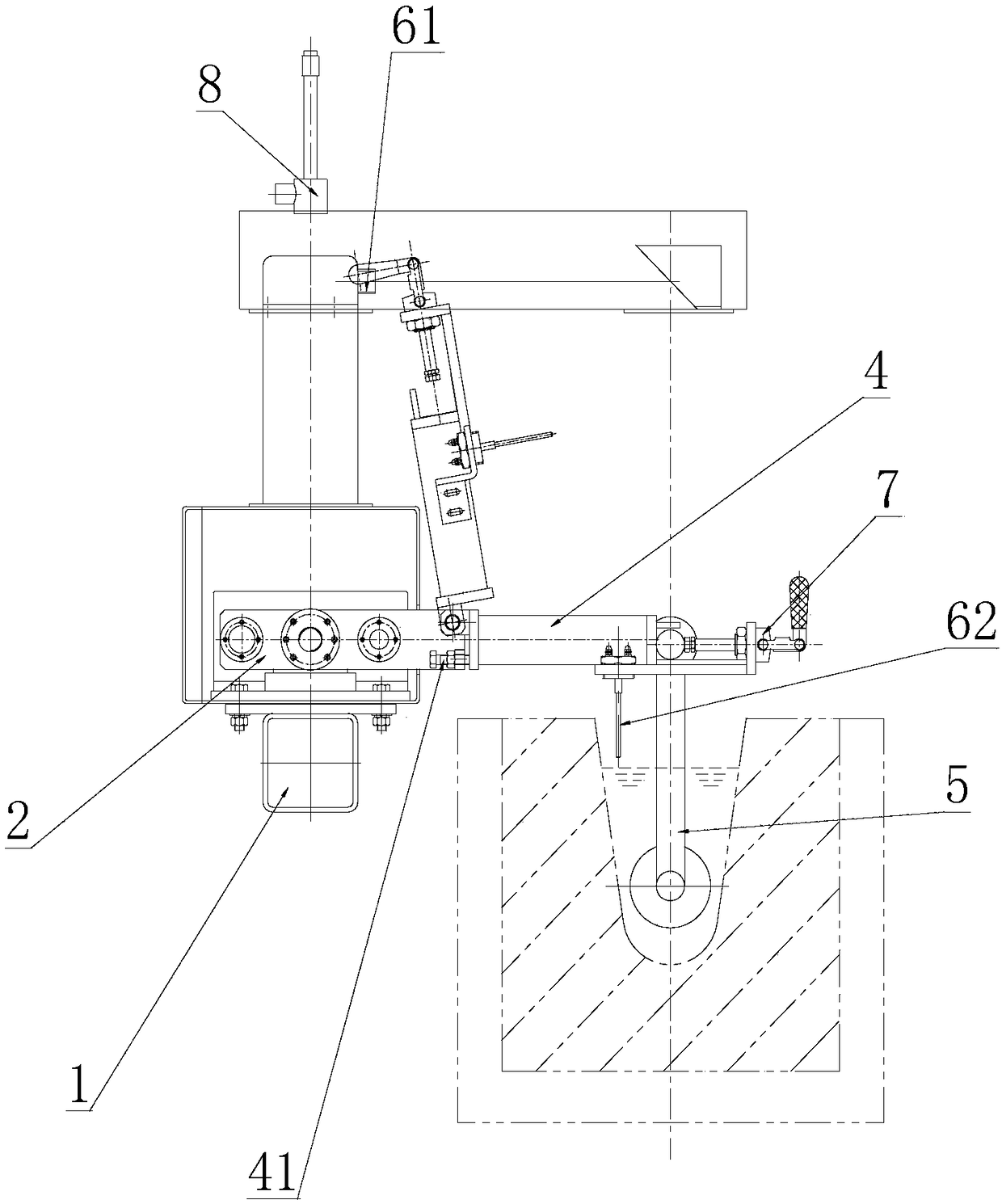
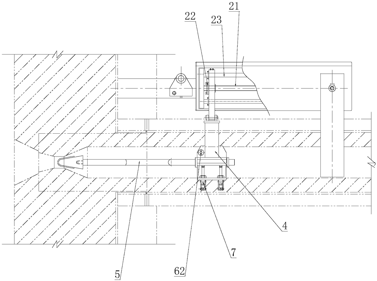
The invention provides an automatic flow control system for a stationary type foundry furnace. The system comprises rotary installation frame fixedly installed on the side wall of a furnace body, a sliding table device installed on the installation frame and driven by a motor, a traction arm connected with the sliding table device, a drill bit assembly which is fixed to the traction arm through alock catch, a detection device arranged on the installation frame and an electrical control system used for electrically controlling the detection device and the sliding table device. The complete high-precision closed-ring control system is formed, high-precision automatic flow control requirements are met, the control precision within the range of -1.5mm-1.5mm of th stationary furnace drainage flow groove liquid surface can be achieved, cast aluminum melt can be stably rotated through a flow groove, the slagging and oxidation air suction phenomena in the foundry process can be reduced, the high-quality foundry technology can be achieved in a matched mode, the highly-integrated device is achieved, installation is easy and convenient, manual and automatic operation is achieved, and the practical function is quite high.

Description

technical field [0001] The invention relates to the technical field of aluminum casting production equipment, in particular to an automatic flow control system for a stationary casting furnace. Background technique [0002] In the casting production process of the aluminum processing industry, various types of fixed holding furnaces are widely used for casting production. During the production process, the melt in the furnace flows out from the flow hole at the bottom of the furnace under the action of gravity, and its flow rate and flow rate are affected by the furnace. The influence of the inner melt depth is always changing. In order to achieve stable casting production, it is necessary to use the drill bit assembly and the flow eye to control the casting liquid level. [0003] At present, the drill bit components for flow control in the fixed furnace are basically controlled manually, which requires the operator to continuously adjust the position of the drill bit compon...

Claims


Application Information

Patent Timeline
Patent Type & Authority Applications(China)
IPC IPC(8): B22D37/00
CPCB22D37/00
Inventor 余志华
Owner SUZHOU ZHONGYANG THERMAL ENERGY TECH CO LTD
Why Eureka
Try Eureka