Tool for laser-assisted machining of inner holes and method for adjusting laser incident angle

A laser-assisted, inner hole technology, applied in the direction of manufacturing tools, metal processing equipment, laser welding equipment, etc., can solve the problems of increasing tool wear, failing to achieve the quality of the machined surface, unable to solve the inner hole processing, etc., to solve the problem of the tool bar The temperature rise is too high, and the effect of freeing the incident point is solved

Active Publication Date: 2020-12-11
HARBIN UNIV OF SCI & TECH
View PDF4 Cites 0 Cited by
  • Summary
  • Abstract
  • Description
  • Claims
  • Application Information

AI Technical Summary

Problems solved by technology

However, laser-assisted processing is rarely used when facing inner hole processing
The whole process of laser-assisted processing needs to adjust the spatial position of the laser. Due to the space limitation of the inner hole processing, the activity space of the laser is limited, so that the laser cannot be accurately irradiated to the surface of the workpiece.
The development of laser-assisted processing has been hindered in the case of inner hole cutting. The existing laser-assisted processing technology cannot solve the problem of inner hole processing, which makes some difficult-to-machine materials increase the wear of the tool and cannot improve the inner hole. Machining efficiency and not up to the standard machined surface quality

Method used


Image

  • Tool for laser-assisted machining of inner holes and method for adjusting laser incident angle
  • Tool for laser-assisted machining of inner holes and method for adjusting laser incident angle
  • Tool for laser-assisted machining of inner holes and method for adjusting laser incident angle

Examples


Embodiment 1

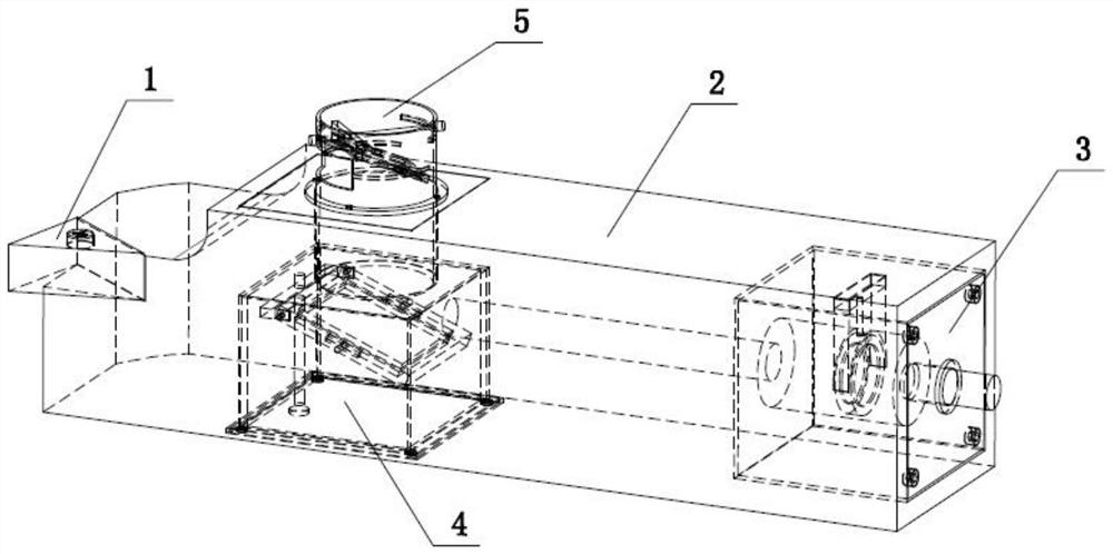
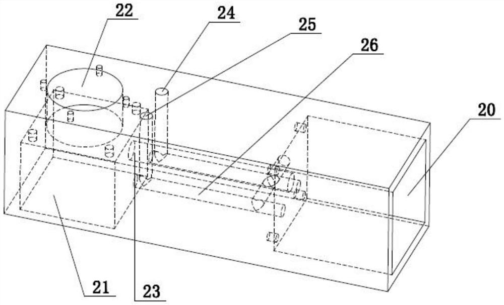
[0040] This embodiment provides a tool for laser-assisted machining of inner holes, such as figure 1 , figure 2 As shown, it includes a cutter head 1, a cutter bar 2, a first module 3, a second module 4 and a third module 5, the cutter head 1 is arranged at the head end of the cutter bar 2, and the tail end of the cutter bar 2 is provided with a first installation groove 20 The first end of the knife bar 2 is provided with a second mounting groove 21 and a third mounting groove 22 communicating with each other, and a first through hole 23 is also provided between the first mounting groove 20 and the second mounting groove 21 to make the two communicate with each other; One module 3 is arranged in the first installation groove 20, the second module 4 is arranged in the second installation groove 21, the third module 5 is arranged in the third installation groove 22; the first module 3 is provided with a convex lens 32, the second The module 4 is provided with a first concave ...

Embodiment 2

[0050] On the basis of the laser-assisted inner hole machining tool provided in Embodiment 1, this embodiment provides a method for adjusting the incident angle of the laser, including the following steps:

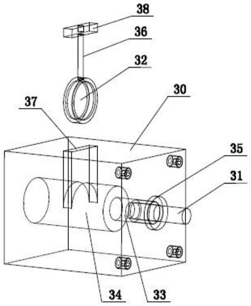
[0051] Step 1. Introduce the laser: the laser fiber 31 passes through the first inner hole 33 and the second inner hole 34 of the first block 30, and the laser passes through the convex lens 32 and then enters the interior of the cutter bar 2, and then enters the second through the first through hole 23. On the glass of the first concave lens 42 in the module 4;

[0052] Step 2, adjust the reflection angle: manually adjust the knob on the first adjustment rod 44 at the bottom of the block bottom plate 41 of the second block 40, so that the mirror of the first concave lens 42 in the second module 4 rotates around the fixed pin 46 , to adjust the reflection angle of the laser.

[0053] Step 3. Adjusting the incident angle: by manually adjusting the knob on the second adjust...


PUM


Abstract

The invention discloses a tool capable of achieving inner hole laser auxiliary machining. The tool comprises a tool bit, a tool rod, a first module, a second module and a third module; the tool bit isarranged at the head end of the tool rod, the tail end of the tool rod is provided with a first mounting groove, a second mounting groove and a third mounting groove which communicate are formed in the head end of the tool rod, a first through hole for communicating the first mounting groove with the second mounting groove is formed between the first mounting groove and the second mounting groove, the first module is arranged in the first mounting groove, the second module is arranged in the second mounting groove, the third module is arranged in the third mounting groove, a convex lens and two concave lenses are integrated in the first module, the second module and the third module, incident laser is subjected to condensation and reflection, the modules are arranged in the tool rod, anda laser device is not limited in inner hole machining space limiting. The invention further discloses a method for adjusting the laser incident angle, the lenses in the modules are subjected to angleadjusting, and flexible adjusting of the laser incident position in a workpiece inner hole can be achieved.

Description

technical field [0001] The invention relates to the technical field of laser-assisted processing, in particular to a tool for laser-assisted processing of an inner hole and a method for adjusting a laser incident angle. Background technique [0002] Laser heating assisted milling technology is to irradiate a high-energy laser beam on the material removal area, increase the local temperature of the workpiece material in a short time, change the cutting performance of the material, and then use the tool for processing. By heating the material, the plasticity of the material is improved, the yield strength is reduced to below the fracture strength, the cutting force is reduced, the tool wear is reduced, and the cutting chatter is reduced, thereby achieving the purpose of improving processing efficiency, reducing cost, and improving the quality of the processed surface. [0003] Laser-assisted processing is suitable for a variety of processing conditions, and it has strong adapt...

Claims


Application Information

Patent Timeline
Patent Type & Authority Patents(China)
IPC IPC(8): B23K26/382B23K26/70
CPCB23K26/382B23K26/702
Inventor 吴雪峰周贤良
Owner HARBIN UNIV OF SCI & TECH
Why Eureka
Try Eureka