Rapid focusing method of visual servo system of robot

A robot vision and servo system technology, applied in the field of focusing, can solve the problems of poor zoom ability, difficult to meet the real-time requirements of visual servo, slow speed, etc., to achieve the effect of ensuring image clarity and shortening the duration of fast automatic focusing

Active Publication Date: 2019-02-12
HARBIN INST OF TECH
View PDF6 Cites 4 Cited by
  • Summary
  • Abstract
  • Description
  • Claims
  • Application Information

AI Technical Summary

Problems solved by technology

[0003] The purpose of the present invention is to solve the existing mechanical focusing technology, which has the problems of poor zoom ability and

Method used


Image

  • Rapid focusing method of visual servo system of robot
  • Rapid focusing method of visual servo system of robot
  • Rapid focusing method of visual servo system of robot

Examples


specific Embodiment approach 1

[0025] A fast focusing method of a robot visual servo system according to the present embodiment, the method is as follows: firstly, collecting the current of multiple groups of liquid cameras with maximum sharpness, and the distance data of the liquid camera from the target object; then, establishing the current and The relationship model between the distances, and the unknown parameters in the model are determined by system identification and parameter fitting methods, and the final relationship model is determined; finally, the distance data between the camera and the target object is obtained and substituted into the determined final relationship model, and inversely Push the current value required by the liquid lens to zoom, and then control the liquid lens to zoom in real time.

specific Embodiment approach 2

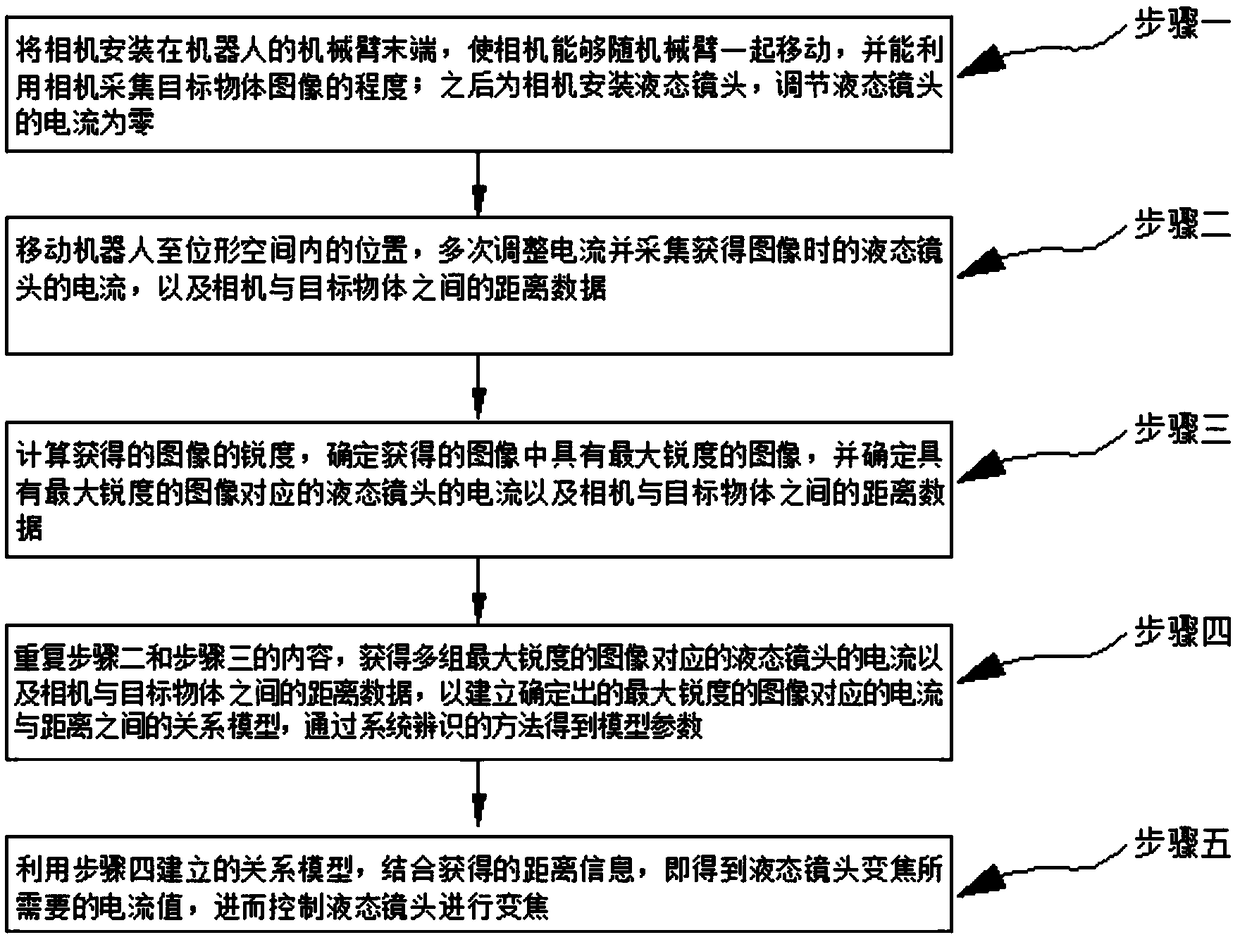
[0026] The difference from Embodiment 1 is that a fast focusing method of a robot visual servo system in this embodiment, such as figure 1 As shown in the flow chart, the method comprises the following steps:

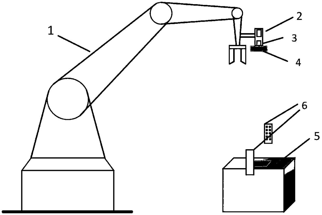
[0027] Step 1. Install the camera at the end of the robotic arm of the robot, so that the camera can move with the robotic arm, and the camera can be used to collect images of the target object; then install a liquid lens for the camera, and adjust the current of the liquid lens to zero;

[0028] Step 2. Move the robot to the position where the target object can be photographed in the configuration space, adjust the current multiple times and collect the current of the liquid lens when the image is obtained, as well as the distance data between the camera and the target object; in the configuration space, Refers to the position where the robot performs the normal shooting work of the target object;

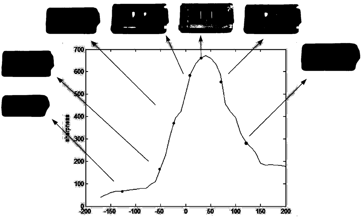
[0029] Step 3, calculating the sharpness of the obtained image, deter...

specific Embodiment approach 3

[0032] The difference from the second specific embodiment is that in the fast focusing method of a robot visual servo system in this embodiment, in the second step, the robot is moved to a position where the target object can be photographed in the configuration space, the current is adjusted multiple times and The process of collecting the current of the liquid lens when the image is obtained, and the distance data between the camera and the target object is as follows:

[0033] Step 21. Move the robot to the configuration space of the manipulator, adjust the camera installed at the end of the manipulator to the position where the target object can be photographed, set the current of the liquid lens to zero, and adjust the camera so that the image in the camera field of view has a relatively high good clarity;

[0034] Step 22: Move the robotic arm, and calculate the vertical distance between the camera and the top surface of the target object according to the robot model; ad...


PUM


Abstract

The invention discloses a rapid focusing method of a visual servo system of a robot, and belongs to the field of image processing. An existing mechanical focusing technology has the problems that thezooming capability is poor and the speed is low, and the real-time requirement of visual servo is difficult to meet. According to the method, a liquid lens is installed at a camera arranged at the tail end of a mechanical arm of the robot; the current of the liquid lens when the image is acquired and the distance data between the camera and a target object are collected for multiple times; the image with the maximum sharpness, the current of the corresponding liquid lens and the distance data between the camera and the target object are determined; the above content is repeated to obtain a plurality of sets of current and distance data with the maximum sharpness, a relation model between the current and the distance of the maximum sharpness is established, and model parameters are obtainedthrough a system identification method; the established relation model is utilized, a current value required by the liquid lens zooming is obtained by combining the distance information, and then theliquid lens is controlled to perform zooming. According to the method, the rapid focusing of the visual servo system and the imaging definition of the target object are ensured.

Description

technical field [0001] The invention relates to a focusing method, in particular to a fast focusing method for a robot visual servo system. Background technique [0002] The technology of using the camera to acquire images, and processing, analyzing and understanding the images to provide feedback information to the robot and control the robot is called visual servo technology. At present, with the proposal and development of the concept of unmanned factories, visual servo technology is more and more widely used in industry. The visual servo system that installs the camera at the end of the robot, the biggest feature is that the camera will move with the end of the robot, and the image changes rapidly. In the visual servo system, the clarity of the image determines the stability and precision of the robot control in the visual servo. Therefore, we need the camera to zoom in real time and quickly to obtain clear images during the movement of the robot, so as to ensure the s...

Claims


Application Information

Patent Timeline
IPC IPC(8): B25J9/16G02B7/36
CPCG02B7/36B25J9/1697
Inventor 林伟阳刘晨璐李湛佟明斯潘惠惠高会军
Owner HARBIN INST OF TECH
Why Eureka
Try Eureka