
Cutting device for rubber ring

A technology of cutting device and apron, which is applied in metal processing and other directions, can solve the problems of low production efficiency, irregular fracture, high labor intensity, etc., and achieve the effect of high production efficiency, large bonding surface and simple structure

Inactive Publication Date: 2019-02-12
李武
View PDF0 Cites 1 Cited by
  • Summary
  • Abstract
  • Description
  • Claims
  • Application Information

AI Technical Summary

Problems solved by technology

[0003] The purpose of the present invention is to overcome the problems of irregular fracture, low production efficiency and high labor intensity in the prior art of manually cutting rubber strips, and provide an air filter rubber ring with simple structure, convenient use and high production efficiency strip cutting device

Method used


Image

  • Cutting device for rubber ring

Examples


Embodiment Construction

[0010] Below in conjunction with accompanying drawing description and specific embodiment, the present invention will be described in further detail:

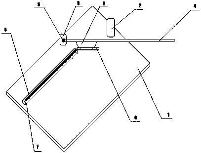
[0011] see figure 1 , a cutting device for rubber rings, including a workbench 1, a support frame 2 is provided on the right side of the workbench 1, a fixing frame 3 is provided at the upper middle of the workbench 1, and the shear rod 4 passes through The rotating shaft 5 is movably connected with the fixed frame 3, the shear bar 4 is provided with a blade 6, the left side of the workbench 1 is provided with a horizontal guide plate 7, and the guide plate 7 is provided with a ruler 8, and the shear bar 4 and the guide plate 7 form an included angle, and the angle range of the included angle is 120 degrees to 180 degrees.

[0012] When in use, install the disc-shaped rubber strip on the support frame 2 on the right side of the workbench 1, first cut out a fracture with the shear bar 4 at the starting point of the rubber strip...


PUM


Abstract

The invention discloses a cutting device for a rubber ring. The cutting device for the rubber ring comprises a workbench. A support frame is arranged at the right side of the workbench; a fixed frameis arranged at an upper middle position of the workbench; a cutting rod is movably connected with the fixed frame through a rotary shaft; a blade is arranged on the cutting rod; a horizontal guide plate is arranged at the left side of the workbench; a straight ruler is arranged on the guide plate; an inclined angle is formed between the cutting rod and the guide plate; and the angle range of the inclined angle is 120 degrees to 180 degrees.

Description

technical field [0001] The invention relates to a rubber ring cutting device. Background technique [0002] The existing air filter apron is cut off with a strip-shaped rubber strip, and then bonded to the end cover of the air filter. Generally, it is cut with scissors according to a certain length, and then the two ends are bonded with sticky water. The length of the apron is determined by Straightedge to draw a line. However, the fracture cut with scissors is irregular, resulting in poor bonding effect of the bonded joints, and often there will be uneven joints, and the irregular joints will easily cause air leakage at the joints, which will eventually cause the air filter to be installed in the car assembly. As a result, the seal is not tight and dust enters. In addition, the ruler marking speed is slow, the production efficiency is low, and the labor intensity of the workers is high. Contents of the invention [0003] The purpose of the present invention is to overc...

Claims


Application Information

Patent Timeline
Patent Type & Authority Applications(China)
IPC IPC(8): B26D1/30B26D5/10B26D7/28B26D7/20
CPCB26D1/305B26D5/10B26D7/20B26D7/28
Inventor 李武
Owner 李武
Learn More