Building wear-resistant material cutting device with polishing function

A wear-resistant material and cutting device technology, applied in the field of building wear-resistant materials, can solve the problems of inability to adjust the cutting angle, no waste collection device, inconvenient installation and disassembly, etc. The effect of efficiency

Inactive Publication Date: 2019-02-12
WUHU HUANGSHANSONG IND FLOOR NEW MATERIAL CO LTD
View PDF4 Cites 3 Cited by
  • Summary
  • Abstract
  • Description
  • Claims
  • Application Information

AI Technical Summary

Problems solved by technology

[0004] The purpose of the present invention is to provide a cutting device for building wear-resistant materials with a grinding function, to solve the problem that the cutting angle of the existing cutting device for building wear-resistant materials with a grinding function proposed in the background technology cannot be adjusted, and for Vertical cutting requires repeated lifting operations to reduce processing efficiency, it is inconvenient to install and disassemble, and the device is fixed, which makes it not flexible enough, and there is no problem with waste collection devices

Method used


Image

  • Building wear-resistant material cutting device with polishing function
  • Building wear-resistant material cutting device with polishing function
  • Building wear-resistant material cutting device with polishing function

Examples


Embodiment Construction

[0022] The following will clearly and completely describe the technical solutions in the embodiments of the present invention with reference to the accompanying drawings in the embodiments of the present invention. Obviously, the described embodiments are only some, not all, embodiments of the present invention. Based on the embodiments of the present invention, all other embodiments obtained by persons of ordinary skill in the art without making creative efforts belong to the protection scope of the present invention.

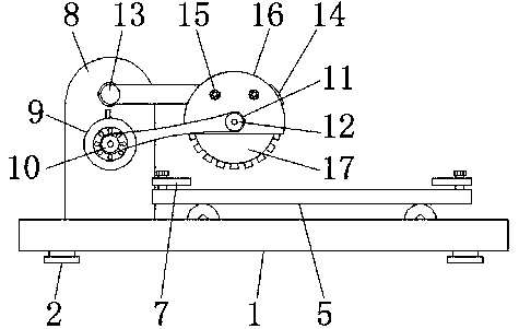
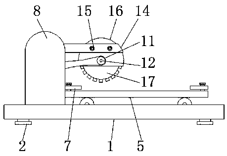
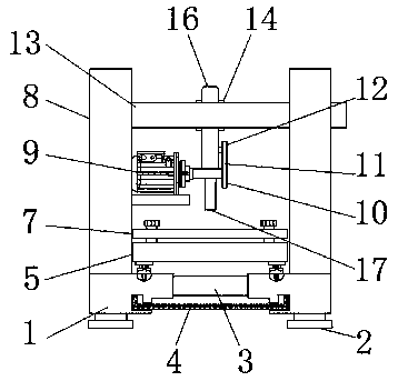
[0023] see Figure 1-4 , the present invention provides a technical solution: a cutting device for building wear-resistant materials with a grinding function, including a bottom plate 1, a cushion block 2, a sub-rod 3, a collection tank 4, a processing plate 5, a slot hole 6, a fixed Clamping plate 7, side plate 8, motor 9, first gear plate 10, transmission chain 11, second gear plate 12, rotating rod 13, fixed rod 14, fixing bolt 15, outer casing 16 and cutti...


PUM


Abstract

The invention discloses a building wear-resistant material cutting device with a polishing function. The building wear-resistant material cutting device comprises a bottom plate, a processing plate, arotating rod and a cutting piece, wherein the left and right ends of the lower surface of the bottom plate are fixedly provided with cushion blocks, a gathering groove is formed below a pawl lever, the processing plate is located above the bottom plate, the left and right sides of the upper portion of the processing plate are in threaded connection with a fixing clamping plate, a motor is fixedlyarranged in the middle of the surface of the inner side of a side plate, the outer side of a first gear plate is connected with a conveyor chain in an engaged manner, the rotating rod is connected tothe interior of the inner surface of the upper end of the side plate in a penetrating manner, the right end of a fixing rod is symmetrically provided with fixing bolts, and the fixing bolts are in threaded connection with an outer shell, and the cutting piece is located on the inner side of the lower end of the outer shell. The building wear-resistant material cutting device with the polishing function can adjust the cutting angle, does not need repeated lifting operation, improves the processing efficiency, and is convenient to install and disassemble. The device is movably installed, and awaste collecting device is arranged.

Description

technical field [0001] The invention relates to the related technical field of building wear-resistant materials, in particular to a cutting device for building wear-resistant materials with a grinding function. Background technique [0002] Building materials can be divided into structural materials, decorative materials and some special materials. There are many places where materials need to be processed on the construction site, among which wood and metal materials are processed the most. In order to make the required shape convenient for the staff Assembly and use often require cutting and grinding, and the quality of processing often determines the quality of the project. Among them, the use of wear-resistant materials is also a relatively wide range, so the processing of wear-resistant materials requires more stringent procedures. [0003] Generally, the cutting angle of the cutting device for building wear-resistant materials with grinding function cannot be adjuste...

Claims


Application Information

Patent Timeline
Patent Type & Authority Applications(China)
IPC IPC(8): B27C5/02B27C5/06B27G3/00B24B9/04B24B9/18B24B41/06B23D19/00B23D33/02B23D33/00
CPCB23D19/00B23D33/00B23D33/02B24B9/04B24B9/18B24B41/06B27C5/02B27C5/06B27G3/00
Inventor 黄小虎
Owner WUHU HUANGSHANSONG IND FLOOR NEW MATERIAL CO LTD
Why Eureka
Try Eureka