Laminator for graphic design

A technology of graphic design and plastic sealing machine, which is applied in the field of machinery, can solve problems such as troublesome operation, uneven packaging quality, and many packaging steps, and achieve the effects of convenient operation, improved packaging effect, and ensuring consistency

Inactive Publication Date: 2019-02-12
泰兴市唯艺传媒广告有限公司
View PDF0 Cites 3 Cited by
  • Summary
  • Abstract
  • Description
  • Claims
  • Application Information

AI Technical Summary

Problems solved by technology

[0003] There are two problems in the existing packaging method: 1. There are many packaging steps, and the operation is more troublesome; 2. The two processes of edge banding and cutting are completely done by hand, resulting in uneven packaging quality

Method used


Image

  • Laminator for graphic design
  • Laminator for graphic design
  • Laminator for graphic design

Examples


Embodiment 1

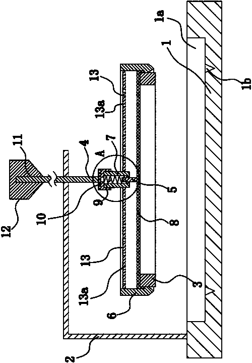
[0032] Such as Figure 1 to Figure 3 Shown, this planar design is made up of base plate 1, support 2, electric heating ring 3, driver 4, connecting rod 5, cutter 6 etc. with plastic sealing machine. Wherein, the cutter 6 is made of heat-conducting material, and the heat-conducting material can be brass, stainless steel and the like. In this embodiment, preferably the cutter 6 is made of stainless steel. The electric heating ring 3 is an existing product, which can be purchased on the market.

[0033] Specifically, the bottom plate 1 is flat, and in actual use, the bottom plate 1 is arranged along a horizontal direction. A placement slot 1a is provided in the middle of the upper side of the bottom plate 1, and the placement slot 1a is preferably square. A relief groove 1b is provided on the bottom wall of the placement groove 1a, the relief groove 1b is square, and the central axes of the relief groove 1b and the placement groove 1a are collinear.

[0034] The bracket 2 is ...

Embodiment 2

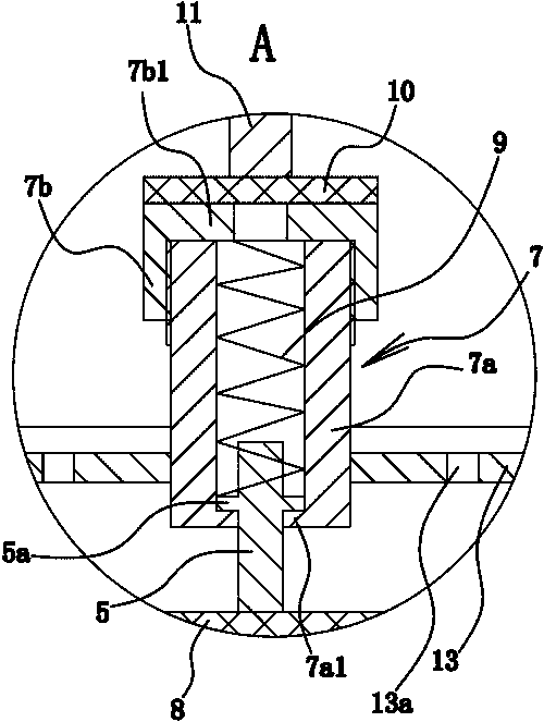
[0042] The structure and principle of the second embodiment are basically the same as that of the first embodiment, except that the driving part 4 is an electric push rod 11, and the electric push rod 11 is fixed on the bracket 2 through the frame, and the rod of the electric push rod 11 The part is fixed with the annular retaining edge 7b1.


PUM


Abstract

The invention provides a laminator for graphic design, and belongs to the technical field of machines. With the laminator for graphic design, the problem that according to a laminating method in the prior art, the laminating quality is poor is solved. The laminator for graphic design comprises a base plate and a support fixed to the base plate. An electric heating ring is horizontally placed on the base plate. A connecting pipe is vertically arranged on the upper part of the electric heating ring. The laminator for graphic design further comprises an actuator capable of driving the connectingpipe to carry out upward and downward translation. A connecting rod is arranged in the lower end of the connecting pipe. The lower end of the connecting rod extends out of the connecting pipe and is fixed to the electric heating ring. An annular limiting seat is arranged on the inner wall of the connecting pipe. An annular convex head is arranged on the outer wall of the connecting rod. A spring used for making the convex head be in the trend of abutting against the limiting seat is further arranged in the connecting pipe. A tubular cutter is arranged outside the electric heating ring in a sleeving manner. The cutter is fixed to the connecting pipe. The lower end of the cutter is of a cutting edge structure, and the position of the cutting edge structure is higher than that of the lower end face of the electric heating ring. The laminator for graphic design has the advantage of being good in laminating quality.

Description

technical field [0001] The invention belongs to the technical field of machinery, and relates to a sealing machine, in particular to a plastic sealing machine for plane design. Background technique [0002] In the sample processing process of advertising design, the final bagging and packaging of advertising design samples is an extremely critical step. The existing packaging method is as follows: first put the sample into the plastic bag, then make the upper side and the lower side of the plastic bag stick together through the contact of the electric heating sheet with the surrounding of the plastic bag to achieve the edge sealing effect, and finally pass Cutting with a cutter to complete the entire packaging process. [0003] There are two problems in the existing packaging method: 1. There are many packaging steps, and the operation is troublesome; 2. The two processes of edge banding and cutting are completely completed by hand, resulting in uneven packaging quality. ...

Claims


Application Information

Patent Timeline
Patent Type & Authority Applications(China)
IPC IPC(8): B65B51/10B65B61/10
CPCB65B51/10B65B61/10
Inventor 范晓莉张煜
Owner 泰兴市唯艺传媒广告有限公司
Why Eureka
Try Eureka