Slurry treatment system

A treatment system and mud technology, applied in sludge treatment, water/sludge/sewage treatment, dehydration/drying/thickened sludge treatment, etc., can solve the problems of collection difficulties, damage, large size, etc., and save volume and space , Avoid accumulation and solidification, long service life

Active Publication Date: 2019-02-12
CHANGSHA UNIVERSITY OF SCIENCE AND TECHNOLOGY
View PDF11 Cites 1 Cited by
  • Summary
  • Abstract
  • Description
  • Claims
  • Application Information

AI Technical Summary

Problems solved by technology

[0004] 1. The outer cylinder of the centrifuge in the prior art needs to be larger in size, because the outer cylinder contains relatively solid mud and needs to be discharged, and there is a waste of space, but the diameter of the outer cylinder cannot be reduced because of the reduction. It is not enough to accommodate a large number of mud parts, so it causes troubles. The solution is often to directly use a large-diameter outer cylinder, but it does not meet the design trend of miniaturization and refinement
[0005] 2. The centrifuge in the prior art lacks maintenance means, and only part of it can be cleaned during cleaning, and there is a cleaning dead angle
[0006] 3. A part of the centrifuge in the prior art is provided with a drain pipe or a liquid collecting pipe, which is often exposed in the drum and is washed by centrifugal particles. When there are stones in the mud, it is easy to rotate and damage the drain pipe; for this reason The solution is often to increase the material hardness of the discharge pipe, but it increases the cost
[0007] 4. There is a discharge valve under the centrifuge in the prior art, but the discharge valve is directly impacted by the centrifuged material, and it is easy to loosen or even be damaged after a long time
[0008] 5. After the centrifuge in the prior art is used for a long time, it will accumulate materials that are difficult to remove, even if it is impacted by water, it cannot be removed
[0009] 6. In the mud treatment system of the prior art, when the conveyor belt is conveying, the material is often randomly dropped onto the conveyor belt, which is uncontrollable, and there is difficulty in collecting the random material.

Method used


Image

  • Slurry treatment system
  • Slurry treatment system
  • Slurry treatment system

Examples


Embodiment Construction

[0037] The present invention will be further described below in conjunction with the accompanying drawings and embodiments.

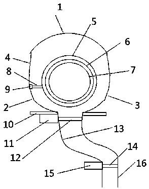
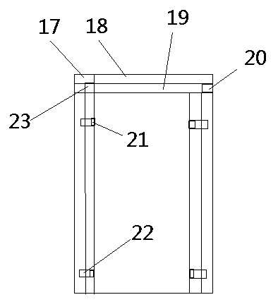
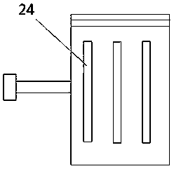
[0038] As shown in the figure: a mud treatment system, including liquid collection tank, conveying pipeline, centrifuge, centrifuge motor, control valve, mixing cylinder, flocculant pump, mud pump, mud tank, mixing cylinder motor, conveyor belt, inlet Mud pipe, discharge valve, bracket; the centrifuge includes first arc, second arc, third arc, connecting section, outer wall, middle wall, inner wall, scraper rod, scraper, multi-functional tank, outer maintenance plate, inner maintenance Pan, liquid discharge purge port, top wall of liquid discharge pipe, liquid discharge pipe, auxiliary purge port, mud discharge grid; the mud pump transports the mud in the mud pool to the mixing cylinder, and the flocculant pump transports the flocculant to the mixing tank. The motor of the mixing cylinder drives the blades inside the mixing cylinder to stir. The control...


PUM


Abstract

The invention provides a slurry treatment system. The slurry treatment system comprises a liquid collection box, a conveying pipeline, a centrifuge, a centrifuge motor, a control valve, a mixing barrel, a flocculating agent pump, a slurry pump, a slurry tank, a mixing barrel motor, a conveyor belt, a slurry feeding pipe, an unloading valve and a bracket, wherein the centrifuge comprises a first arc, a second arc, a third arc, a connection section, an outer wall, a middle wall, an inner wall, a scraping knife rod, a scraping knife, a multifunctional groove, an outer maintenance disc, an inner maintenance disc, a liquid discharging blowing opening, a liquid discharging pipe top wall, a liquid discharging pipe, an auxiliary blowing opening and a slurry discharging grid, wherein the slurry pump is used for conveying slurry in the slurry tank into the mixing barrel; the flocculating agent pump is used for conveying a flocculating agent into the mixing barrel; the mixing barrel motor is usedfor driving blades in the mixing barrel to stir; the control valve is connected between the mixing barrel and the centrifuge; the slurry enters the centrifuge through the slurry feeding pipe; liquiddischarged from the centrifuge enters the liquid collection box through the conveying pipeline; the slurry discharged from the centrifuge falls onto the conveyor belt through the unloading valve; theslurry treatment system further comprises a controller.

Description

technical field [0001] The invention relates to the related field of mud treatment, in particular to a mud treatment system. Background technique [0002] With the development of science and technology and economic development, the amount of mud used is increasing. At present, the mud in the city mainly comes from construction engineering mud, municipal sludge and river silt. With the continuous acceleration of urbanization, high-rise, super There are more and more constructions of various projects such as high-rise buildings, subways, expressways, and large bridges, and the amount of mud produced is also increasing. At present, there are mainly the following ways to deal with mud: 1) Tanker truck (mud truck) for external transportation. This method is to directly lift the mud generated on site into the mud truck through the mud pump, and transport the mud to the outskirts of the city through the mud truck. 2) On-site sedimentation and drying, this method needs to build a s...

Claims


Application Information

Patent Timeline
Patent Type & Authority Applications(China)
IPC IPC(8): C02F11/121C02F11/127C02F11/14
CPCC02F11/121C02F11/127C02F11/14C02F2303/06
Inventor 尹来容易继军周荡黄龙杜荣华
Owner CHANGSHA UNIVERSITY OF SCIENCE AND TECHNOLOGY
Why Eureka
Try Eureka