Retractable ditch trestle bridge

A telescopic and channel technology, applied in the directions of portable bridges, bridges, bridge parts, etc., can solve the problems that can not meet the needs of construction personnel and management personnel patrol inspection, the method of erecting the trestle is not uniform, and the maintenance cost is high. Light, good comprehensive economic benefits, low installation cost

Inactive Publication Date: 2019-02-12
QINGHAI POWER TRANSMISSION & TRANSFORMATION ENG +2
View PDF5 Cites 5 Cited by
  • Summary
  • Abstract
  • Description
  • Claims
  • Application Information

AI Technical Summary

Problems solved by technology

[0002] With the continuous improvement of standardization requirements for safe and civilized construction, the ditch trestle on the construction site can no longer meet the needs of construction personnel and management personnel for inspection. At present, there are no installation examples of light ditch trestles in domestic substation and converter station projects, which is in line with the current standardization requirements. There is a certain gap, and the construction methods of trestle bridges in each project are not uniform
At present, most trench trestles are made of ordinary carbon steel materials. Carbon steel materials are easy to rust in a humid environment, difficult to clean, high maintenance costs, and high installation costs.

Method used


Image

  • Retractable ditch trestle bridge
  • Retractable ditch trestle bridge
  • Retractable ditch trestle bridge

Examples


Embodiment 1

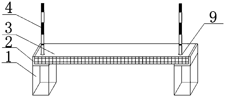
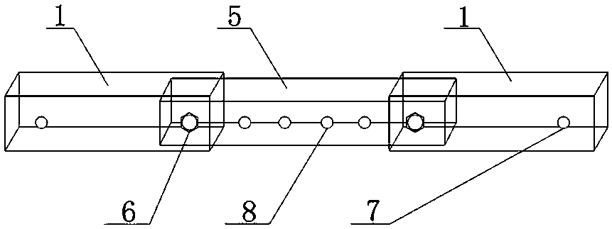
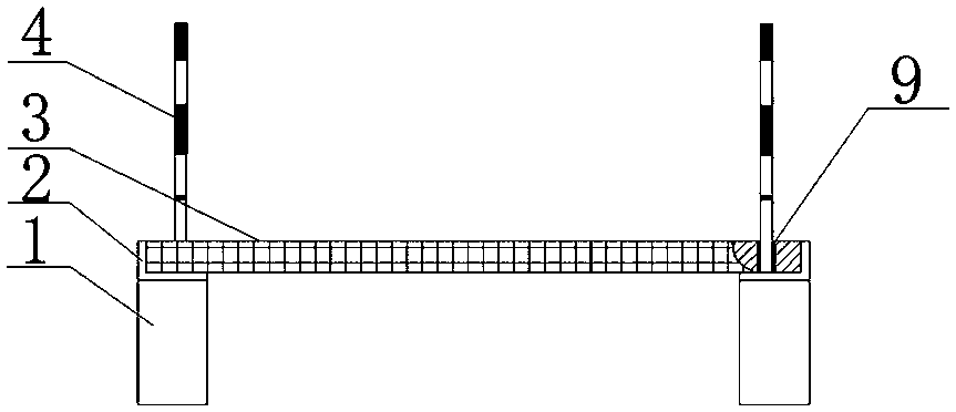
[0013] Example 1, such as Figure 1-Figure 2 As shown, the present invention provides a retractable channel trestle bridge, its structure is: there are two steel girders (1), the two ends of the steel girders (1) are provided with through holes A (7), and the two steel girders (1) They are connected by a sleeve (5), and the sleeve (5) is provided with a through hole B (8), and the limit bolt (6) connects the steel beam (1) through the through hole A (7) and the through hole B (8). ) is fixed with the sleeve (5), the length of the steel beam (1) can be adjusted through the sleeve (5) and the limit bolt (6), the limit angle steel (2) is fixed on the steel beam (1), and the steel beam (1) The bridge deck (3) is fixed with the limit angle steel (2), and sockets (9) are respectively provided on both sides of the bridge deck (3), and vertical railings (4) are inserted in the sockets (9), and the vertical railings (4) are fixed There are railings (10).

[0014] The bridge deck (3) ...

Embodiment 2

[0018] Example 2, such as Figure 1-Figure 2 As shown, the present invention provides a retractable channel trestle bridge, its structure is: there are two steel girders (1), the two ends of the steel girders (1) are provided with through holes A (7), and the two steel girders (1) They are connected by a sleeve (5), and the sleeve (5) is provided with a through hole B (8), and the limit bolt (6) connects the steel beam (1) through the through hole A (7) and the through hole B (8). ) is fixed with the sleeve (5), the length of the steel beam (1) can be adjusted through the sleeve (5) and the limit bolt (6), the limit angle steel (2) is fixed on the steel beam (1), and the steel beam (1) The bridge deck (3) is fixed with the limit angle steel (2), and sockets (9) are respectively provided on both sides of the bridge deck (3), and vertical railings (4) are inserted in the sockets (9), and the vertical railings (4) are fixed There are railings (10).

[0019] The bridge deck (3) ...

Embodiment 3

[0023] Example 3, such as Figure 1-Figure 2 As shown, the present invention provides a retractable channel trestle bridge, its structure is: there are two steel girders (1), the two ends of the steel girders (1) are provided with through holes A (7), and the two steel girders (1) They are connected by a sleeve (5), and the sleeve (5) is provided with a through hole B (8), and the limit bolt (6) connects the steel beam (1) through the through hole A (7) and the through hole B (8). ) is fixed with the sleeve (5), the length of the steel beam (1) can be adjusted through the sleeve (5) and the limit bolt (6), the limit angle steel (2) is fixed on the steel beam (1), and the steel beam (1) The bridge deck (3) is fixed with the limit angle steel (2), and sockets (9) are respectively provided on both sides of the bridge deck (3), and vertical railings (4) are inserted in the sockets (9), and the vertical railings (4) are fixed There are railings (10).

[0024] The bridge deck (3) ...


PUM


Abstract

The invention discloses a retractable ditch trestle bridge, and relates to the technical field of bridges. The retractable ditch trestle bridge structurally comprises two steel beams, through holes Aare formed in both ends of the steel beams, the two steel beams are connected through a casing pipe, through holes B are formed in the casing pipe, the steel beams and the casing pipe are fixed through the through holes A and through holes B with limit bolts, and the length of the steel beams can be adjusted through the casing pipe and the limit bolts; and limited angle steel is fixed to the steelbeams, the steel beams are fixed to a bridge deck through the limit angle steel, inserting openings are separately formed in both sides of the bridge deck, vertical railings are separately inserted into the inserting openings, and horizontal railings are fixed to the vertical railings. The retractable ditch trestle bridge has the beneficial effects that finished glass fiber reinforced plastic products are adopted for on-site assembly, the installation work efficiency of the ditch trestle bridge is improved, inspection is convenient, and the defects of time consumption, labor consumption, difficult movement, non-durability and the like in the installation of a steel trestle bridge on a current construction site can be effectively overcome; and glass fiber reinforced plastic grilles are adopted for the bridge deck, and the glass steel grilles have the advantages of corrosion resistance, light weight, high strength, aging resistance, flame retardance, better comprehensive economic benefits, low installation cost and the like.

Description

technical field [0001] The invention relates to the technical field of bridges, in particular to a retractable channel trestle bridge. Background technique [0002] With the continuous improvement of standardization requirements for safe and civilized construction, the ditch trestle on the construction site can no longer meet the needs of construction personnel and management personnel for inspection. At present, there are no installation examples of light ditch trestles in domestic substation and converter station projects, which is in line with the current standardization requirements. There is a certain gap, and the construction methods of trestle bridges in each project are not uniform. At present, most trench trestles are made of ordinary carbon steel materials. Carbon steel materials are easy to rust in a humid environment, difficult to clean, high maintenance costs, and high installation costs. Contents of the invention [0003] In view of the above problems, the p...

Claims


Application Information

Patent Timeline
Patent Type & Authority Applications(China)
IPC IPC(8): E01D15/12E01D19/00E01D19/12E01D19/10E01D19/02
CPCE01D15/124E01D19/005
Inventor 曾光昌姜建华张启发王永明吕志鹏李永刚段有龙李涓陈守玺李世海
Owner QINGHAI POWER TRANSMISSION & TRANSFORMATION ENG
Why Eureka
Try Eureka