Supercharge Your Innovation With Domain-Expert AI Agents!
Heat recovery type cooling system used for fire grate
What is Al technical title?
Al technical title is built by PatSnap Al team. It summarizes the technical point description of the patent document.
A cooling system and heat recovery technology, which is applied in the direction of grates, grates, incinerators, etc. of hollow grates, can solve the problems of poor cooling effect and achieve the effect of increasing feed water temperature, easy cooling temperature, and controlling cooling temperature
Pending Publication Date: 2019-02-12
SHANGHAI MINGHUA ELECTRIC POWER TECH & ENG +1
View PDF0 Cites 4 Cited by
Summary
Abstract
Description
Claims
Application Information
AI Technical Summary
This helps you quickly interpret patents by identifying the three key elements:
Image
Click on the blue label to locate the original text in one second.
Reading with bidirectional positioning of images and text.
Examples
Embodiment Construction
[0018] The present invention will be described in detail below in conjunction with the accompanying drawings and specific embodiments.
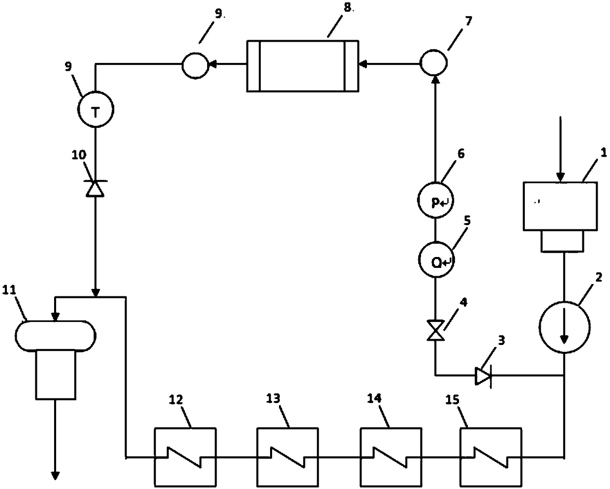
[0019] see figure 1 ,热力系统的电站汽轮机做功后蒸汽进入凝汽器1,蒸汽放热后变成水,水经凝泵2依次送入各级低加12、13、14、15,低加利用汽轮机抽汽加热凝结水,升至一定温度后进入除氧器11,除氧器加热后的水进入锅炉进一步集中加热形成过热蒸汽,过热蒸汽推动汽轮机做功,汽水流程。
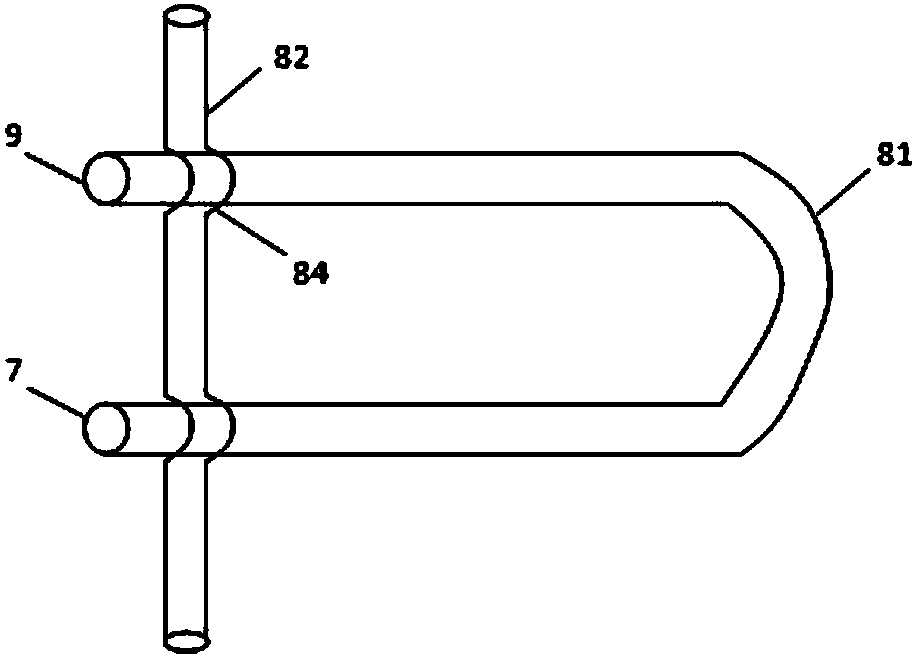
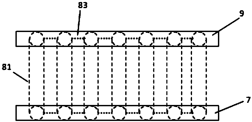
[0022] see figure 2 ,在本发明的一个实施例中,管式炉排8包括并行管束81、炉墙水冷壁管82。管式炉排8在进口联箱7、出口联箱9中间形成纵向并行管束81,进口联箱7、出口联箱9都处在炉墙水冷壁管82的外侧,管排中间管束81处在炉墙水冷壁管82的内侧,水冷壁管82与炉排管束81交叉处跳管,跳管部分形成弯管84,形成十字形固定。
PUM
Abstract
The invention provides a heat recovery type cooling system used for a fire grate. The heat recovery type cooling system comprises a branch pipeline, an inlet header, a cooling pipeline and an outlet header. The branch pipeline is connected with a condensate pump outlet of a thermal system so that condensate water can be conveniently taken out. The inlet header is connected with the branch pipelinementioned above. The cooling pipeline is connected with the inlet header. The condensate water entering the inlet header enters the cooling pipeline to be used for cooling the tubular fire grate. Theoutlet header is connected with the cooling pipeline. The condensate water cooling the tubular fire grate is collected to the outlet header, is then conveyed to a deaerator from the outlet header, and reenters the thermal system. According to the cooling system, the tubular fire grate is cooled through the condensate water, the cooling effect is good, and the cooling temperature is easy to control; in addition, according to the system, the fire grate arranged in a furnace is also ingeniously used for absorbing radiation heat, and cooling water is heated after the fire grate is heated; and inthis way, the high-temperature cooling water enters a heat recovery system, the feed-water temperature is increased, the system thermal efficiency is also improved, and the energy conservation effectis achieved.
Application Information
Patent Timeline
Application Date:The date an application was filed.
Publication Date:The date a patent or application was officially published.
First Publication Date:The earliest publication date of a patent with the same application number.
Issue Date:Publication date of the patent grant document.
PCT Entry Date:The Entry date of PCT National Phase.
Estimated Expiry Date:The statutory expiry date of a patent right according to the Patent Law, and it is the longest term of protection that the patent right can achieve without the termination of the patent right due to other reasons(Term extension factor has been taken into account ).
Invalid Date:Actual expiry date is based on effective date or publication date of legal transaction data of invalid patent.
