

An efficient parallel layer cutting method for STL model based on co-spot welding scheduling
A layer-cutting and model-based technology, applied in the field of additive manufacturing, can solve problems such as reduced layer-cutting efficiency and complex model-cutting accuracy, and achieve the effects of reducing construction time, improving layer-cutting efficiency, and improving layer-cutting efficiency
- Summary
- Abstract
- Description
- Claims
- Application Information
AI Technical Summary
Problems solved by technology
Method used
Image

Examples
Embodiment Construction
[0024] In order to illustrate the technical scheme and technical purpose of the present invention, the present invention will be further introduced below in conjunction with the accompanying drawings and specific embodiments.
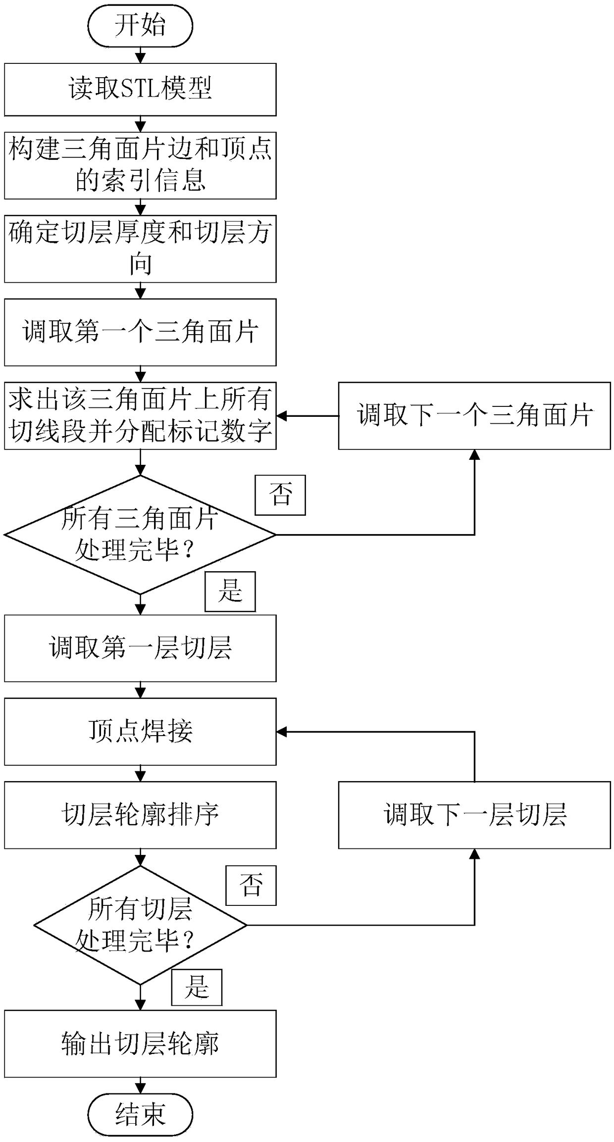
[0025] combine figure 1 , a kind of STL model high-efficiency parallel layer-slicing method based on co-point welding sorting of the present invention, comprises the following steps:
[0026] Step 1. Read the STL model and construct the index information of the vertices and edges of the triangle face
[0027] 1.1. Create a storage container:
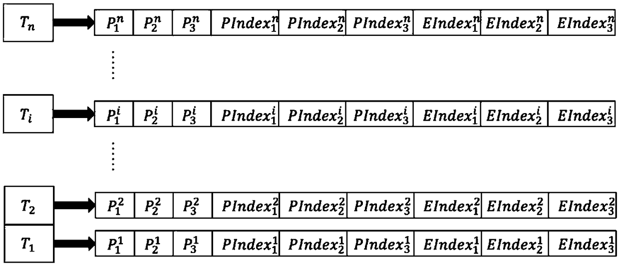
[0028] Create an associative container PointToIndex for storing vertices and vertex indexes, and an associative container EdgeToIndex for storing edges and edge indexes. The two associative containers are initially empty, that is, no elements are stored. In addition, to store the coordinates of the three vertices of the triangular patch (P 1 ,P 2 ,P 3 ), the indices of the three vertices (PIndex 1 、PIndex 2...
PUM
 Abstract
Description
Claims
Application Information