
Electrically scanned X-ray tube

An X-ray tube and electronic scanning technology, applied in the field of X-ray tubes, can solve problems such as cone heart beam artifacts

Pending Publication Date: 2019-02-12
麦默真空技术无锡有限公司
View PDF0 Cites 0 Cited by
  • Summary
  • Abstract
  • Description
  • Claims
  • Application Information

AI Technical Summary

Problems solved by technology

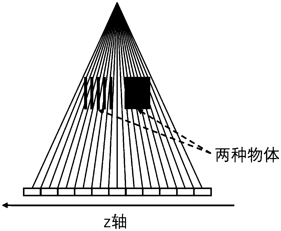
For the cone beam CT system based on the traditional single-ray source X-ray tube, the projection data of the two are the same, resulting in cone beam artifacts

Method used


Image

  • Electrically scanned X-ray tube
  • Electrically scanned X-ray tube
  • Electrically scanned X-ray tube

Examples


Embodiment 1

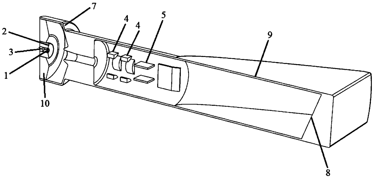
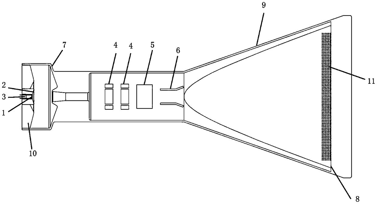
[0027] Embodiment 1 provides an electronically scanned X-ray tube, the structure of which is shown in FIG. 2( a ). The electronic scanning X-ray tube includes a cathode assembly, an electric focusing deflection assembly and an anode assembly. The cathode assembly is used to generate electron beams and pre-focus the electron beams; after the electron beams enter the drift channel, they are deflected and focused under the action of the electric focusing deflection assembly, and finally hit the target disk of the anode assembly, and emit X-rays.

[0028] Specifically, please refer to Figure 2(a) and Figure 2(b) at the same time, the cathode assembly includes an electron emission source 1, a focusing electrode 2 and an insulating ceramic 3; wherein the electron emission source 1 is located in the focusing electrode 2 , the electron beam emitted from the electron emission source 1 is initially focused by the focusing electric field generated by the focusing electrode. The pins of...

Embodiment 2

[0037] The second embodiment provides an electronic scanning X-ray tube, including a cathode assembly, an electric focusing deflection assembly and an anode assembly. The difference from the first embodiment is that in the second embodiment, the electric focus deflection assembly includes two electric quadrupole lenses 4 and a horizontal deflection assembly 6 . The first or second electric quadrupole lens can focus and vertically deflect the electron beam at the same time. On the basis of the original focusing voltage, an additional positive voltage is applied to the electrode 41, and an additional negative voltage is applied to the electrode 43, please refer to Figure 5 , forming an electric field in the direction indicated by the dotted arrow. The electron beam passing therethrough will be deflected toward the electrode 41 in the vertical direction. With the opposite voltage setting, the electron beam is deflected toward the electrode 42 . By replacing the vertical defle...

Embodiment 3

[0039] Embodiment 3 provides another electronic scanning X-ray tube, including a cathode assembly, an electric focus deflection assembly, and an anode assembly. The difference from the first embodiment is that in the third embodiment, the electric focus deflection assembly includes two electric quadrupole lenses 4 and a horizontal deflection assembly 6 . The electronically scanned X-ray tube provided in the third embodiment eliminates the vertical deflection component, so as to realize the electronically scanned linear X-ray tube.


PUM


Abstract

The invention discloses an electrically scanned X-ray tube, and belongs to the technical field of X-rays. The electrically scanned X-ray tube comprises a cathode assembly, an electrical focusing deflection assembly and an anode assembly, wherein the cathode assembly is used for generating an electron beam and pre-focusing the electron beam; and the electrical focusing deflection assembly focuses the electron beam, produces deflections in different degrees and finally impinges the X-rays at different positions on a target disk of the anode assembly, thereby implementing a multi-focus X-ray source. When an object is subjected to image radiation, multiple groups of narrow beam X-rays can be adopted, so that the influence of scattered radiation is effectively reduced, and the contrast and thedefinition of an image are improved; and furthermore, a uniform optical dimension within an entire field angle is guaranteed, and uniform space resolution of the image is guaranteed. If the electrically scanned X-ray tube is applied to a CT (Computer Tomography) system, the multi-focus X-ray source is adopted in the Z direction for radiation sampling, so that the problem of a tap web beam artifactcan be effectively solved.

Description

technical field [0001] The invention relates to the technical field of X-rays, in particular to an electronic scanning X-ray tube. Background technique [0002] X-ray tubes are used to generate X-rays and play an important role in fields such as medical diagnosis, safety inspection and non-destructive testing. The basic principle of the X-ray tube is that the thermal electrons excited by the heating of the cathode filament hit the target disk under the action of the cathode and anode acceleration electric field. About 1% of the energy is converted into X-rays, while the remaining 99% is converted into heat energy, causing the temperature of the impacted part to rise rapidly. In the fixed anode X-ray tube, the electrons continue to hit the same position, the local temperature rises rapidly, and the continuous loading power is very low; the rotating anode X-ray tube adopts the method that the anode bearing drives the anode target disk to rotate at high speed in the vacuum tub...

Claims


Application Information

Patent Timeline
IPC IPC(8): H01J35/14H01J35/30
CPCH01J35/14H01J35/30
Inventor 叶华伟曹红光王啸方奇
Owner 麦默真空技术无锡有限公司
Learn More