Medical automatic drainage device
An automatic drainage tube technology, which is applied in the direction of suction equipment, other medical equipment, hypodermic injection equipment, etc., can solve the problems of increasing the burden on medical staff and patients' families, failing to follow the doctor's expected method, and difficulty in ensuring the drainage effect, etc., to improve Safety and stability, drainage effect guarantee, effect of reducing work load
- Summary
- Abstract
- Description
- Claims
- Application Information
AI Technical Summary
Problems solved by technology
Method used
Image
Examples
Embodiment 1
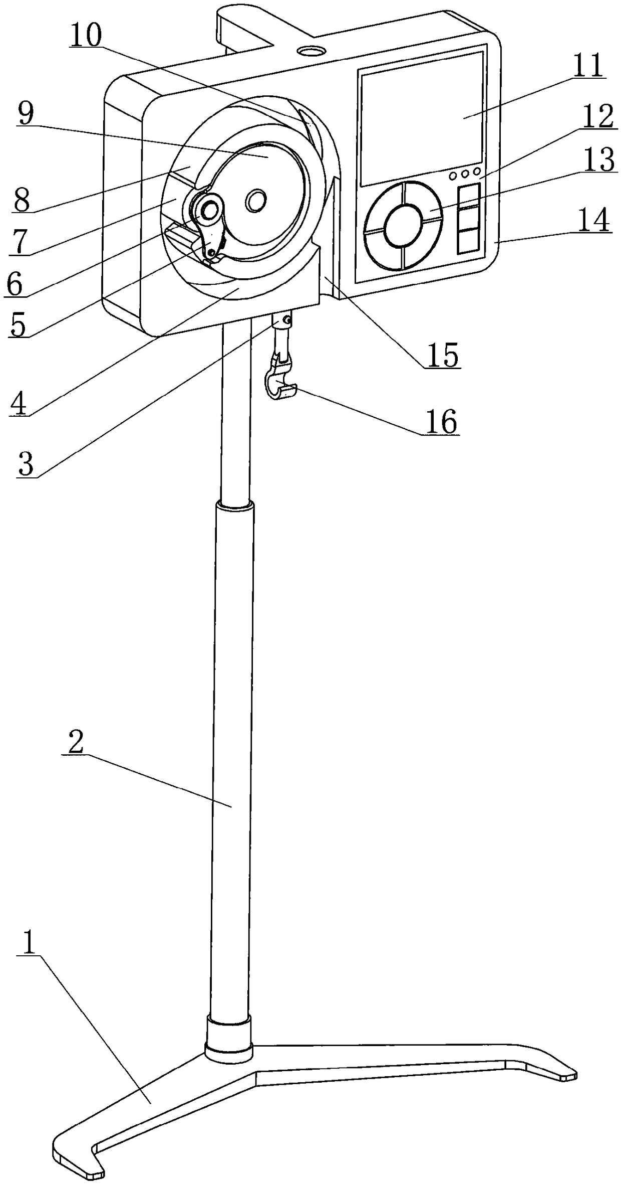
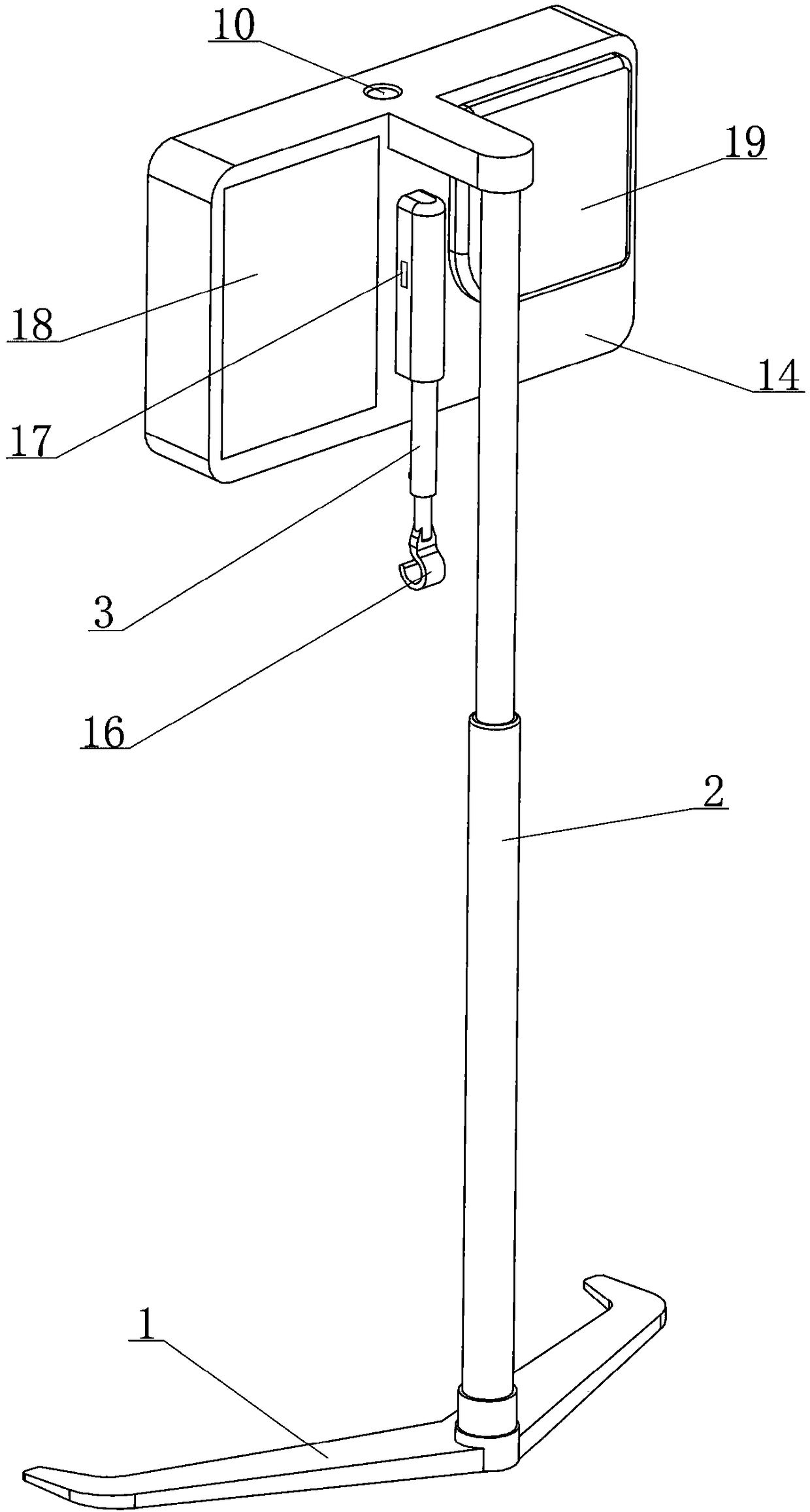
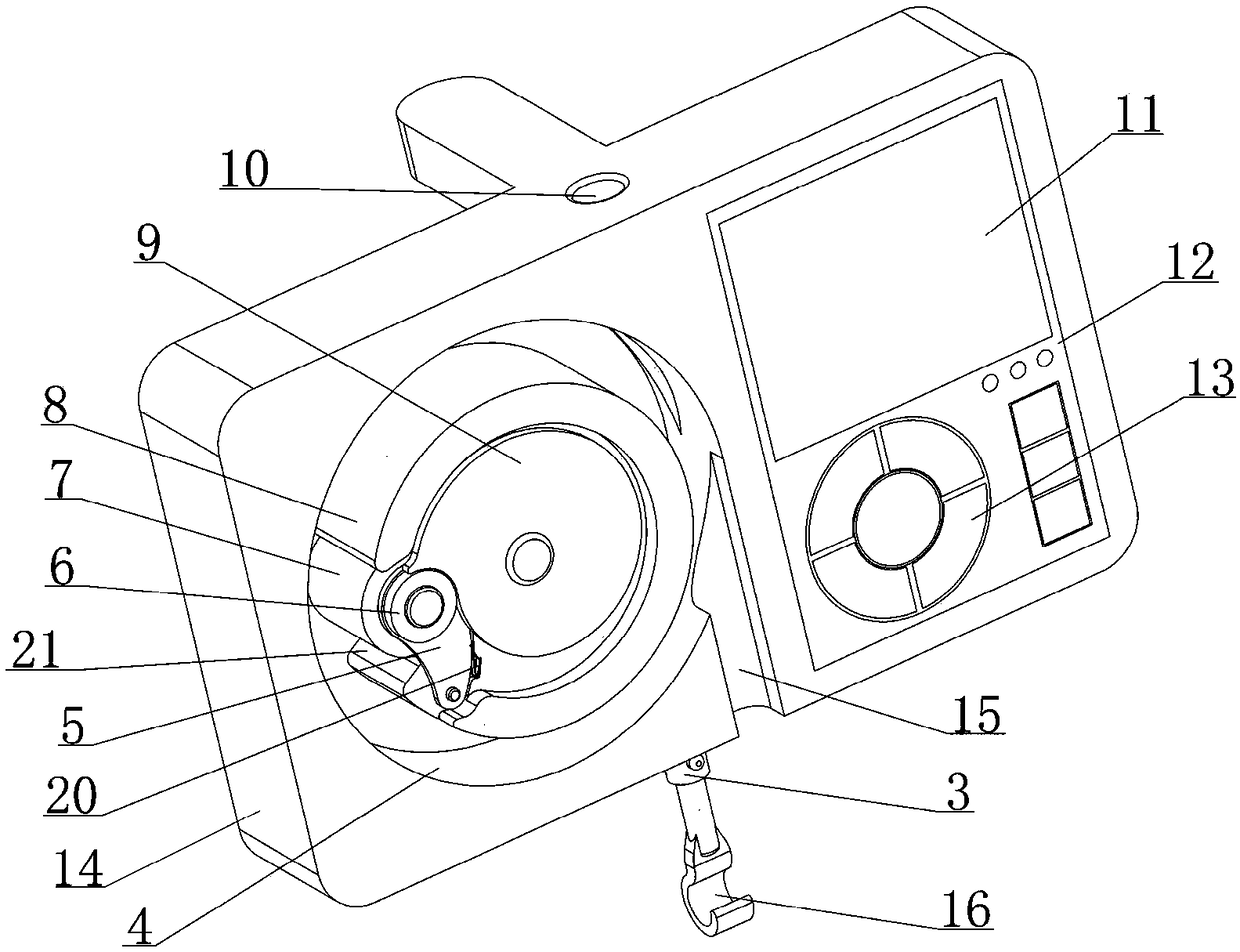
[0040] see figure 1 , 2 As shown, a medical automatic drainage device disclosed in this embodiment is composed of a bracket assembly, a weighted suspension assembly 3, a drainage adjustment assembly, a controller 12 and a power supply part 18;
[0041] Among them, see figure 1 , 2 As shown, the bracket assembly is composed of a base 1, a column 2 and a mounting plate 14; ; The placement plate 14 is used to provide support and installation space for other components;
[0042] Among them, see figure 2 , 9 , 10, the weight-based suspension assembly 3 is supported by the placement plate 14, with a built-in load cell 17, and a suspension part 16 is provided at the lower end; Provide the only support and make the drainage bag 26 hang below the placement plate 14, which can adjust the height of the drainage bag 26, and the load cell 17 outputs a weight signal that can reflect the changing state of the fluid weight in the drainage bag 26;
[0043] Among them, see image 3 , ...
Embodiment 2
[0080] see Figure 4 , 5 As shown, in the medical automatic drainage device disclosed in the foregoing embodiments, the cross-section of the introduction hole 10 is circular, so as to ensure the integrity of the side wall of the recess 4 to the greatest extent, based on the circular hole adopted by the introduction hole 10 structure, when the drainage tube 25 is introduced into the annular gap, it is necessary to pass the tail end of the drainage tube 25 through the introduction hole 10 from front to back, and the operation is not convenient enough; Plate 14 has the following improvements:
[0081] Such as Figure 14 , 15 As shown, the set plate 14 has a square groove 35 which can fully expose the introduction hole 10 on the front side wall, and a sliding baffle 33 with a moving stroke is defined in the square groove 35; when the sliding baffle 33 is in its stroke At the beginning, it will block the front side of the introduction hole 10 and can compress the drainage tube ...
Embodiment 3
[0084] see figure 2 , 9 , 10, in the medical automatic drainage device disclosed in embodiment 1, the accuracy of the weighing signal output by the load cell 17 is greatly affected by whether the medical automatic drainage device is placed horizontally; Although the difference can be solved by laying objects under the base 1, the operation is cumbersome and time-consuming. For this reason, this embodiment is based on the structure of the medical automatic drainage device disclosed in Embodiment 1. With the following improvements:
[0085] Such as Figure 16 , 17 As shown, the rear side of the placement plate 14 is fixed with a first rotating shaft 38 extending horizontally backward, and a swing seat 39 is fixed by the first rotating shaft 38 so as to be able to swing left and right in a small range; The upper end is connected with the swing seat 39 through the second rotating shaft 37 so that the weight-based suspension assembly 3 can swing back and forth in a small range...
PUM
 Abstract
Description
Claims
Application Information
 - R&D
- Intellectual Property
- Life Sciences
- Materials
- Tech Scout
- Unparalleled Data Quality
- Higher Quality Content
- 60% Fewer Hallucinations
Browse by: Latest US Patents, China's latest patents, Technical Efficacy Thesaurus, Application Domain, Technology Topic, Popular Technical Reports.
© 2025 PatSnap. All rights reserved.Legal|Privacy policy|Modern Slavery Act Transparency Statement|Sitemap|About US| Contact US: help@patsnap.com


