COB light source production wire welding soldering iron with protecting function

A protective function and soldering iron technology, which is applied to soldering irons, manufacturing tools, welding equipment, etc., can solve problems such as easy wear on the surface of soldering iron needles, failure to meet work requirements, and burnt devices, etc., to achieve safe and reliable charging and discharging, and time-saving operation Efforts to save labor and prolong service life

Inactive Publication Date: 2019-02-15
开平市翔丰光电科技有限公司
View PDF0 Cites 0 Cited by
  • Summary
  • Abstract
  • Description
  • Claims
  • Application Information

AI Technical Summary

Problems solved by technology

[0004] The purpose of the present invention is to provide a COB light source production wire soldering iron with a protective function, to solve the problem that the wire soldering iron proposed in the background technology is rarely provided with a lithium battery, and most of them are plugged in for use. It cannot be used under the environment, and cannot meet the work needs in more urgent situations. There are no pinholes, and the surface of the soldering iron needle is easy to wear and burn the device.

Method used


Image

  • COB light source production wire welding soldering iron with protecting function
  • COB light source production wire welding soldering iron with protecting function
  • COB light source production wire welding soldering iron with protecting function

Examples


Embodiment Construction

[0019] The following will clearly and completely describe the technical solutions in the embodiments of the present invention with reference to the accompanying drawings in the embodiments of the present invention. Obviously, the described embodiments are only some, not all, embodiments of the present invention. Based on the embodiments of the present invention, all other embodiments obtained by persons of ordinary skill in the art without making creative efforts belong to the protection scope of the present invention.

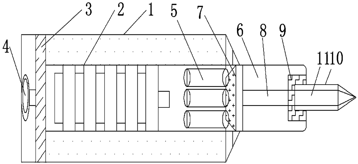
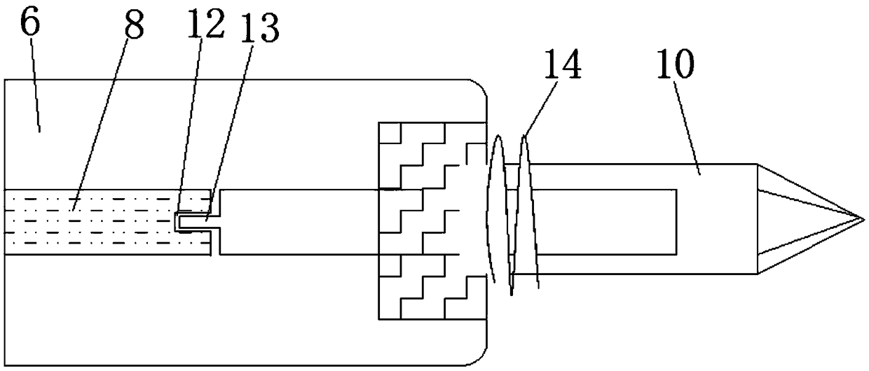
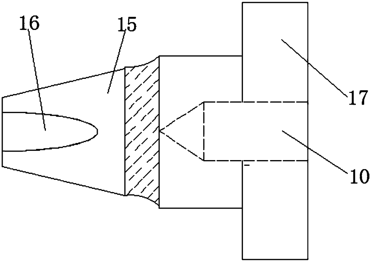
[0020] see Figure 1-3 , the present invention provides a technical solution: a wire welding soldering iron for COB light source production with protection function, including a soldering iron body 1, a lithium battery 2, a fixing plate 3, a charging port 4, a cable tube 5, a rod tube 6, a heat conducting Block 7, soldering iron core 8, internal thread groove 9, soldering iron tip 10, soldering iron needle 11, card slot 12, card block 13, external thread conve...


PUM


Abstract

The invention discloses COB light source production wire welding soldering iron with a protecting function. The COB light source production wire welding soldering iron comprises a soldering iron bodyand a clamping groove; a lithium battery is installed in the soldering iron body, and a fixing plate is fixedly connected to the left end of the lithium battery; a charging port is arranged in the left outer wall of the soldering iron body; cable pipes are installed in the soldering iron body, a rod pipe is installed at the right ends of the cable pipes, and a heat conduction block is installed atthe left end of the interior of the rod pipe; and an inner threaded groove is formed in the right outer wall of the rod pipe, a soldering iron head is connected to the inner wall of the inner threaded groove in a meshing mode, a soldering iron needle is installed in the soldering iron head, and outer threaded convex teeth are arranged on the outer wall of the left end of the soldering iron head.According to the COB light source production wire welding soldering iron with the protecting function, the clamping groove is formed, the clamping groove and a clamping block are designed to be of a clamped structure and can better cooperate with disassembling and assembling of the soldering iron head, assembling is convenient, use of a new soldering iron head is not influenced, and the cost is reduced through partial replacement.

Description

technical field [0001] The invention relates to the technical field of COB light source production, in particular to a wire welding soldering iron with protection function for COB light source production. Background technique [0002] The COB chip-on-board process is first to cover the placement point of the silicon chip with thermally conductive epoxy resin on the surface of the substrate, and then place the silicon chip directly on the surface of the substrate, heat treatment until the silicon chip is firmly fixed on the substrate, and then use the method of wire bonding The electrical connection is directly established between the silicon chip and the substrate. The COB light source is a high-efficiency integrated surface light source technology that directly attaches the LED chip to the mirror metal substrate with high reflectivity. This technology eliminates the concept of the bracket, no electroplating, no reflow soldering , No patch process, the wire bonding soldering...

Claims


Application Information

Patent Timeline
Patent Type & Authority Applications(China)
IPC IPC(8): B23K3/03
CPCB23K3/0338B23K3/0369
Inventor 张文聪
Owner 开平市翔丰光电科技有限公司
Why Eureka
Try Eureka