Machine tool assisted mobile device for numerically-controlled machine tool

A technology of CNC machine tools and auxiliary movement, applied in the field of CNC machine tools, can solve the problems of laborious handling, large size and danger of CNC machine tools, and achieve the effects of strengthening shock absorption, reducing loss and reducing vibration.

Active Publication Date: 2019-02-15
楼先富
View PDF5 Cites 3 Cited by
  • Summary
  • Abstract
  • Description
  • Claims
  • Application Information

AI Technical Summary

Problems solved by technology

[0002] CNC lathes are relatively common mechanical equipment in mechanical processing equipment, so they are widely used. In order to facilitate fixing, a base is generally installed at the bottom of existing CNC machine tools. Now, a public document with the publication number CN203045307U discloses a document , it is very convenient to assemble and fix the base and adjust the level of the base. There is no need to lift the base to install and fix it with a driving car or a jack. The anchor bolt socket and the anchor nut can be installed directly through the opening under the base, which greatly reduces the working time. It also saves manpower and material resources, improves work efficiency, greatly reduces the requirements for site equipment, and makes the design more user-friendly; however, when installing and disassembling CNC machine tools, or adjusting their positions in the factory building, they need Mobile, but the CNC machine tool is large in size, and it is very laborious and dangerous to carry

Method used


Image

  • Machine tool assisted mobile device for numerically-controlled machine tool
  • Machine tool assisted mobile device for numerically-controlled machine tool
  • Machine tool assisted mobile device for numerically-controlled machine tool

Examples


Embodiment Construction

[0027] In order to enable those skilled in the art to better understand the solutions of the present invention, the technical solutions in the embodiments of the present invention will be clearly and completely described below in conjunction with the drawings in the embodiments of the present invention. Obviously, the described embodiments are only It is a part of embodiments of the present invention, but not all embodiments. Based on the embodiments of the present invention, all other embodiments obtained by persons of ordinary skill in the art without making creative efforts shall fall within the protection scope of the present invention.

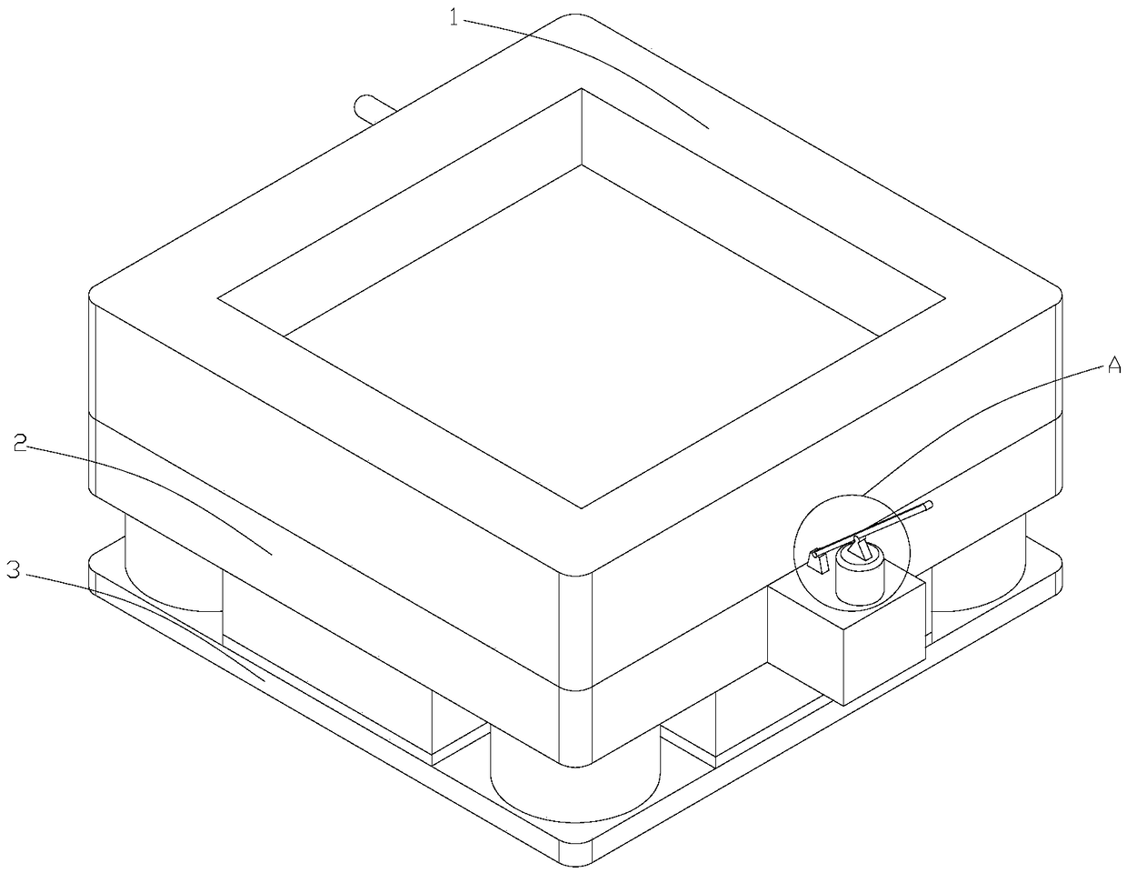
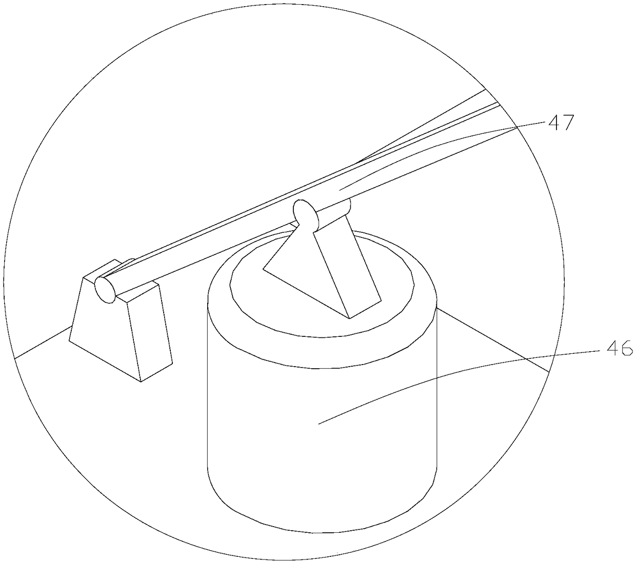
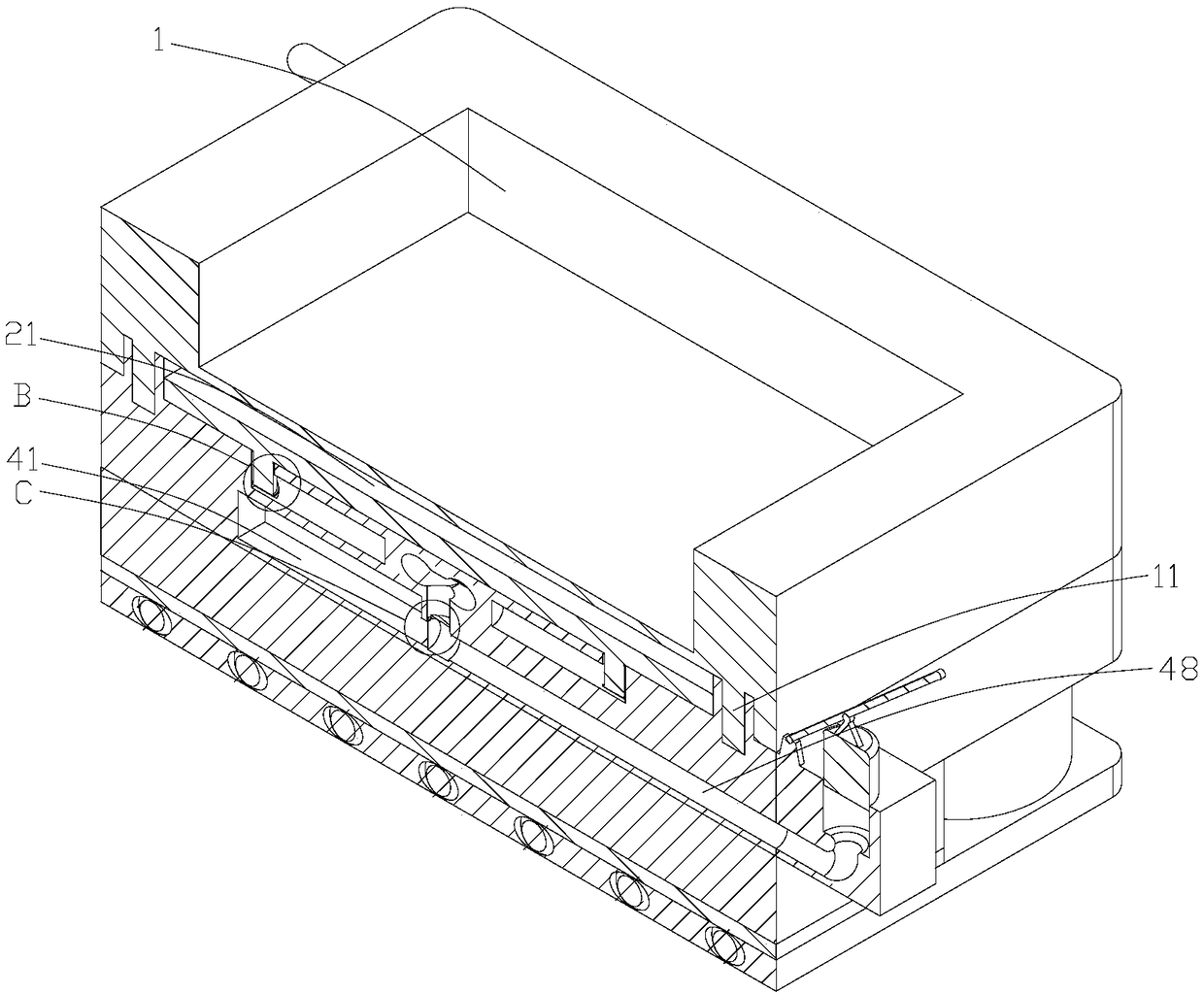
[0028] Such as Figure 1-13As shown, a machine tool auxiliary mobile device for a CNC machine tool, including a fixed chassis 1 for placing a CNC machine tool, a brake seat 2 for braking the CNC machine tool, and a mobile base 3 for assisting the movement of the CNC machine tool, A hydraulic damping mechanism for reducing the vibration o...


PUM


Abstract

The invention discloses a machine tool assisted mobile device for a numerically-controlled machine tool. The machine tool assisted mobile device comprises a fixed chassis for placing the numerically-controlled machine tool, a brake base for braking the numerically-controlled machine tool and a moving base for assisting the movement of the numerically-controlled machine tool. A hydraulic damping mechanism for reducing the vibration of the numerically-controlled machine tool is arranged between the fixed chassis and the brake base, a hydraulic brake mechanism for controlling the movement of thenumerically-controlled machine tool is disposed between the brake base and the moving base, and the movable base is provided with a plurality of rolling members which can rotate arbitrarily. The arrangement of the hydraulic damping mechanism enables the numerically-controlled machine tool to obtain effective cushioning under working conditions, the vibration generated when the numerically-controlled machine tool works is reduced, the noise generated by the vibration is reduced, the comfort of the working environment is improved, the hydraulic brake mechanism and the rolling members are arranged to enable the numerically-controlled machine tool to be moved easily, the efficiency for moving the numerically-controlled machine tool is improved, immediate braking can be further performed, and the automatic movement of the numerically-controlled machine tool is avoided.

Description

technical field [0001] The invention belongs to the field of numerical control machine tools, and in particular relates to a machine tool auxiliary mobile device for numerical control machine tools. Background technique [0002] CNC lathes are relatively common mechanical equipment in mechanical processing equipment, so they are widely used. In order to facilitate fixing, a base is generally installed at the bottom of existing CNC machine tools. Now, a public document with the publication number CN203045307U discloses a document , it is very convenient to assemble and fix the base and adjust the level of the base. There is no need to lift the base to install and fix it with a driving car or a jack. The anchor bolt socket and the anchor nut can be installed directly through the opening under the base, which greatly reduces the working time. It also saves manpower and material resources, improves work efficiency, greatly reduces the requirements for site equipment, and makes t...

Claims


Application Information

Patent Timeline
Patent Type & Authority Applications(China)
IPC IPC(8): B23Q1/01B23Q11/00
CPCB23Q1/01B23Q11/0032
Inventor 陈豪吴高国江小兵
Owner 楼先富
Why Eureka
Try Eureka