Side driving lifting roller bed with low energy consumption and high stability

A high-stability, low-energy-consumption technology, applied to roller tables, conveyor objects, transportation and packaging, etc., can solve the problems of large space occupation, high energy consumption, and unstable operation, and achieve energy saving, cylinder diameter reduction, The effect of reducing air consumption

Pending Publication Date: 2019-02-15
HARBIN SHIMADA BIG BIRD IND
View PDF14 Cites 2 Cited by
  • Summary
  • Abstract
  • Description
  • Claims
  • Application Information

AI Technical Summary

Problems solved by technology

[0003] In order to solve the problems of large space occupation, high energy consumption and unstable operation of the existing lifting roller structure, the present invention further proposes a side-driven lifting roller table with low energy consumption and high stability

Method used


Image

  • Side driving lifting roller bed with low energy consumption and high stability
  • Side driving lifting roller bed with low energy consumption and high stability
  • Side driving lifting roller bed with low energy consumption and high stability

Examples


specific Embodiment approach 1

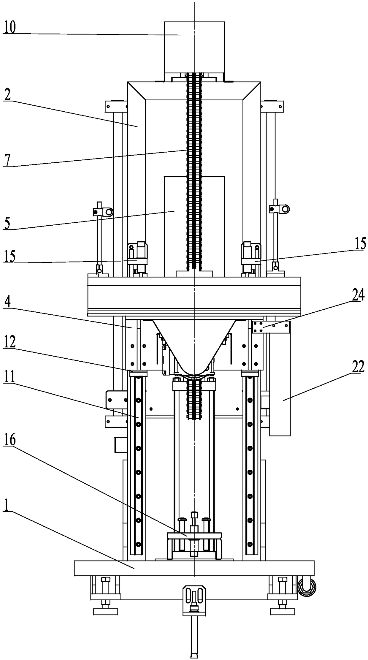
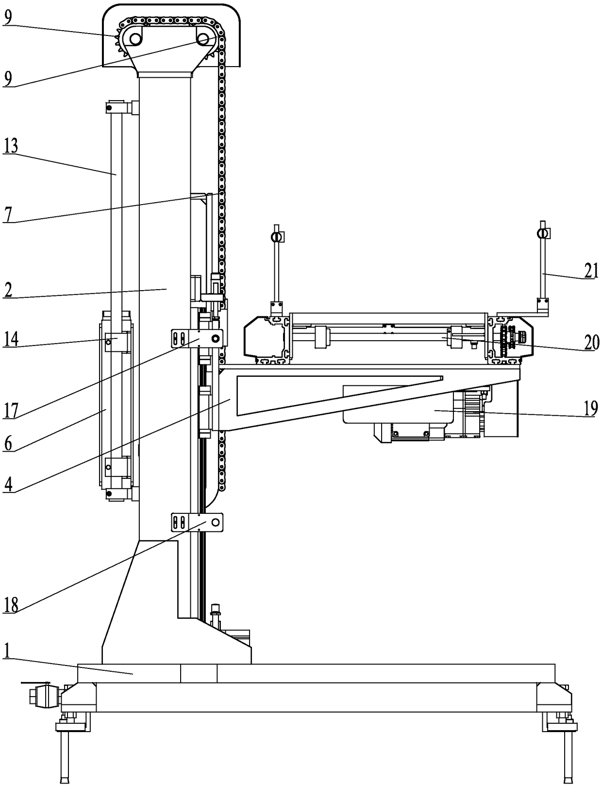
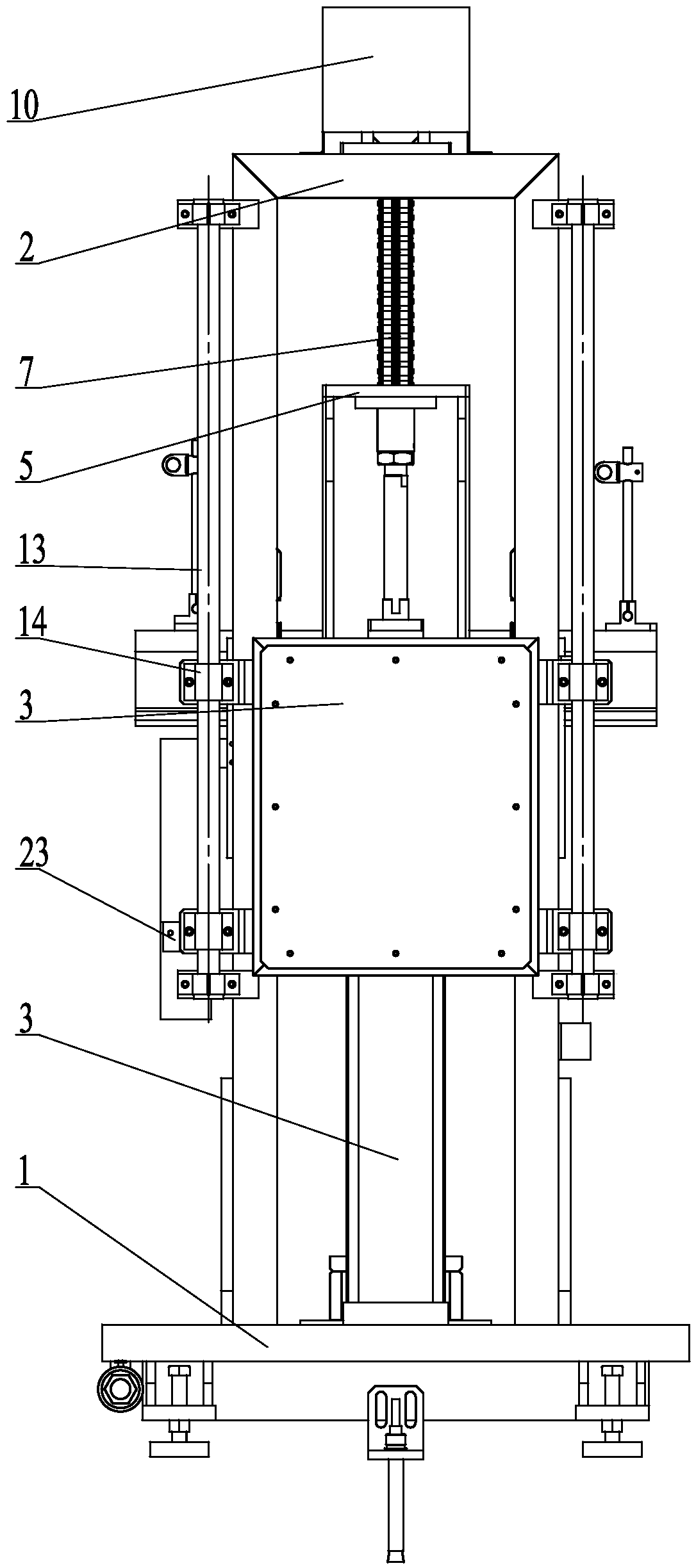
[0012] Specific implementation mode one: combine Figure 1 to Figure 4 Describe this embodiment. A side-mounted lifting roller table with low energy consumption and high stability described in this embodiment includes a base 1, a bracket 2, a cylinder 3, a roller table mounting frame 4, a cylinder connecting frame 5, a counterweight box 6, and a chain 7. The chain transmission mechanism, the roller guide mechanism, the counterweight guide mechanism and the roller table running mechanism, the bracket 2 is vertically fixed on one side of the upper end surface of the base 1, and the middle part of the inside of the bracket 2 is provided with a cylinder 3, and the cylinder 3 is vertical Fixed on the base 1, the roller table mounting frame 4 is horizontally arranged on the front end of the bracket 2, the roller table running mechanism is arranged on the roller table mounting frame 4, and the rear end of the roller table mounting frame 4 is connected to the cylinder 3 through the cyl...

specific Embodiment approach 2

[0014] Specific implementation mode two: combination Figure 1 to Figure 4 Describe this embodiment, the shape of cylinder connecting frame 5 described in this embodiment is L shape, and the inner end face of the short arm of cylinder connecting frame 5 is vertically affixed to the piston rod of cylinder 3, and the outer end face of the long arm of cylinder connecting frame 5 It is affixed to the rear end face of the roller table mounting frame 4. The undisclosed technical features in this embodiment are the same as those in the first embodiment.

[0015] Such design realizes that the roller table mounting frame 4 moves upwards in the vertical direction when the piston rod of the cylinder 3 is stretched out by the design of the cylinder connecting frame 5 .

specific Embodiment approach 3

[0016] Specific implementation mode three: combination Figure 1 to Figure 4 Describe this embodiment, the chain transmission mechanism described in this embodiment includes two upper sprockets 9, each of the front and rear sides of the upper end of the bracket 2 is respectively provided with an upper sprocket 9, the two upper sprockets 9 are horizontally arranged, and the chain 7 is wound around On the outside of two upper sprockets 9. The undisclosed technical features in this embodiment are the same as those in the first or second specific embodiment.


PUM


Abstract

The invention relates to the technical field of roller bed conveying and provides a side driving lifting roller bed with the low energy consumption and high stability in order to solve the problems that an existing lifting roller bed structure is large in occupied space, high in energy consumption and not stable enough in operation. The side driving lifting roller bed comprises a base, a support,a cylinder, a roller bed mounting rack, a cylinder connecting rack, a weight box, a chain, a chain transmission mechanism, a roller bed guide mechanism, a balance weight guide mechanism and a roller bed operating mechanism. The support is vertically and fixedly connected to one side of the upper end face of the base. The cylinder is arranged in the middle portion of the inner side of the support.The roller bed mounting rack is horizontally arranged at the front end of the support. The roller bed operating mechanism is arranged on the roller bed mounting rack. The rear end of the roller bed mounting rack is fixedly connected with a piston rod of the cylinder through the cylinder connecting rack. The weight box is arranged at the rear end of the support. The middle portion of the chain is rotatably connected with the support through the chain transmission mechanism. The two ends of the chain does reciprocating motion in the vertical direction of the support. The weight box and the roller bed mounting rack are fixedly connected with the chain correspondingly. The side driving lifting roller bed is applied to a roller bed conveying line.

Description

technical field [0001] The invention relates to the technical field of roller table transmission, in particular to a side-drive lifting roller table with low energy consumption and high stability. Background technique [0002] The lifting roller table is a common equipment on the conveyor line, which can realize the material conveying of different heights of the roller table. When the height of the lower roller table is low and the stroke of the lifting table is large, the space under the lifting table will be very limited, and the installation of the lifting cylinder is very difficult. , or even impossible. In many cases, this structure is difficult to meet the user's requirements, so the usual practice is to place the lifting cylinder on the upper side of the lifting roller table, but the problem is that the overall height of the equipment is too high, the cylinder bore is large, and the energy consumption High, not smooth enough to run. Contents of the invention [000...

Claims


Application Information

Patent Timeline
Patent Type & Authority Applications(China)
IPC IPC(8): B65G47/64B65G13/12
CPCB65G13/12B65G47/643
Inventor 王飞山王大亮邢忠正李俊堂吴相军
Owner HARBIN SHIMADA BIG BIRD IND
Why Eureka
Try Eureka