Corner curtain wall
A corner curtain wall, corner technology, applied in the direction of walls, building components, buildings, etc., can solve the problems of waste of profiles, inflexible use, waste of resources, etc., and achieve the effect of saving profiles and molds, simple and reliable structure, and reducing consumables.
- Summary
- Abstract
- Description
- Claims
- Application Information
AI Technical Summary
Problems solved by technology
Method used
Image

Examples
Embodiment 1
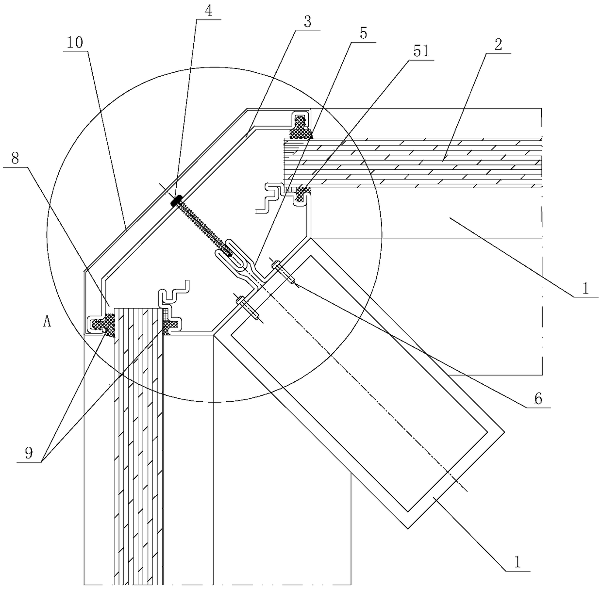
[0036] Such as Figure 1 to Figure 3 As shown, the first embodiment of the corner curtain wall of the present invention, the corner curtain wall includes a keel 1, a curtain wall panel 2, a pressure plate 3, a locking bolt 4 and a connecting abutment 5, and the connecting abutment 5 is connected to the receiving surface of the keel 1, At least one side of the connection base 5 is provided with a receiving part 51 that can be adjusted in advance to adapt to the angle of rotation. The curtain wall panel 2 is carried on the receiving part 51, and the pressing plate 3 is pressed on the curtain wall panel 2 and is connected with the locking bolt 4. Connect the abutment 5 connection. When installing the corner curtain wall, first measure the required corner angle, adjust the angle of the receiving part 51 according to the angle to form a suitable corner angle, then load the curtain wall panel 2 on the receiving part 51, and then press the pressing plate 3 on the curtain wall The bo...
Embodiment 2
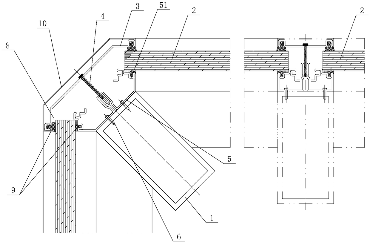
[0044] Such as Figure 4 with Figure 5 As shown, the second embodiment of the corner curtain wall of the present invention, the corner curtain wall is basically the same as Embodiment 1, the only difference is that in this embodiment, a socket for receiving the curtain wall panel 2 is formed between the receiving part 51 and the pressure plate 3 Groove 8, receiving groove 8 is set as female angle groove. Such setting makes the curtain wall form a recessed corner, which is suitable for the installation of the recessed corner.
Embodiment 3
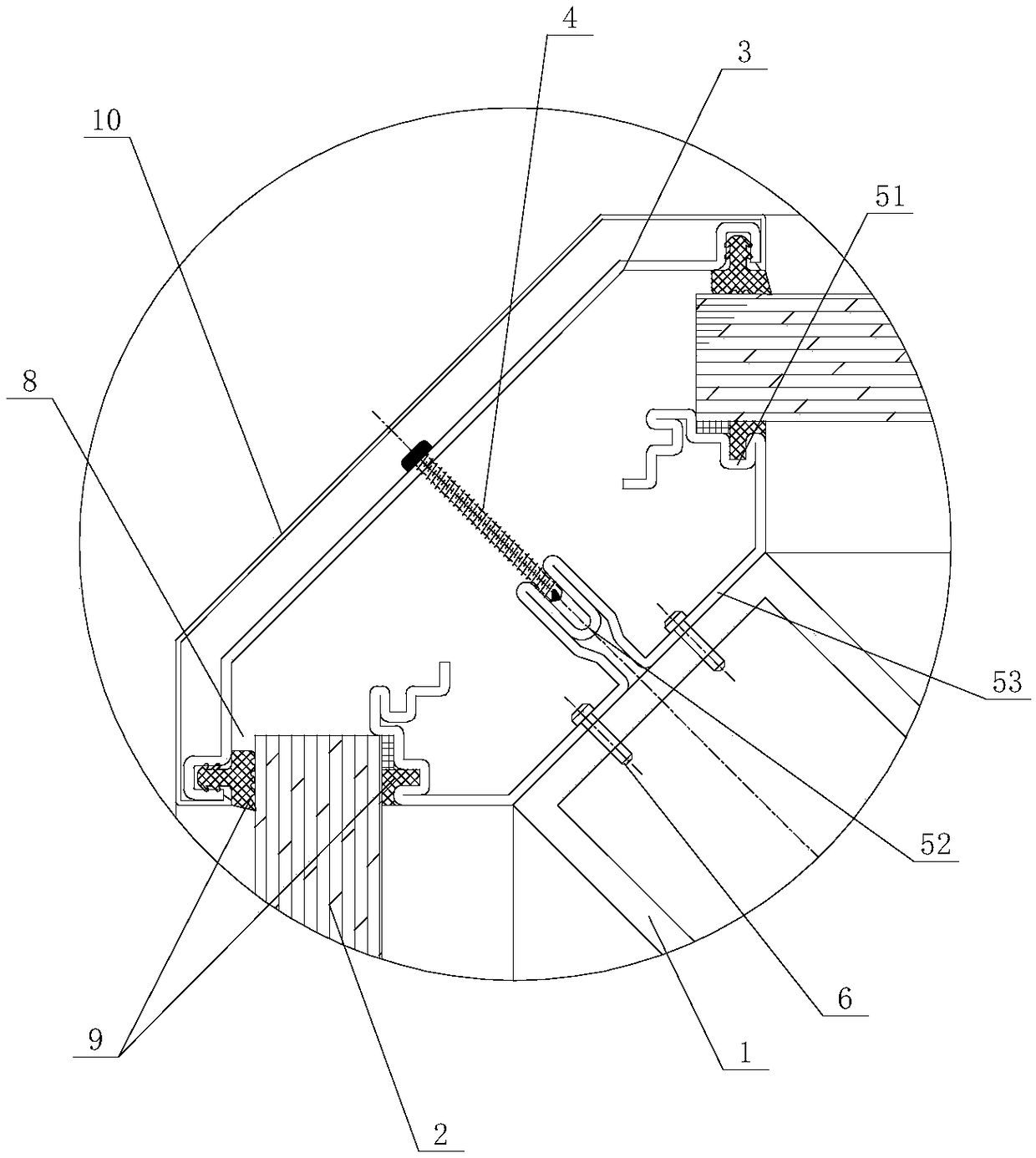
[0046] Such as Figure 6 with Figure 7As shown, the third embodiment of the corner curtain wall of the present invention, the corner curtain wall is basically the same as Embodiment 1, the only difference is that in this embodiment, the connection base 5 includes a connection platform 52, and the bottom plate of the connection platform 52 is set to connect The plate 53 and the top plate of the connecting platform 52 are bent outward to form a receiving portion 51 , the connecting plate 53 is connected to the receiving surface of the keel 1 through the screw 6 , and the locking bolt 4 is connected to the connecting platform 52 . In this structure, the connection plate 53 connecting the abutment 5 is fixed by connecting the bearing surface of the keel 1 through the screw 6, and the receiving portion 51 is bent on the connecting plate 53, and the angle of the receiving portion 51 is pre-bent before installation, and the The curtain wall panel 2 is carried on the receiving part ...
PUM
 Abstract
Description
Claims
Application Information
 - Generate Ideas
- Intellectual Property
- Life Sciences
- Materials
- Tech Scout
- Unparalleled Data Quality
- Higher Quality Content
- 60% Fewer Hallucinations
Browse by: Latest US Patents, China's latest patents, Technical Efficacy Thesaurus, Application Domain, Technology Topic, Popular Technical Reports.
© 2025 PatSnap. All rights reserved.Legal|Privacy policy|Modern Slavery Act Transparency Statement|Sitemap|About US| Contact US: help@patsnap.com