
High-energy CT ultra-deep layer well drilling and fracturing integrated engineering test equipment

A test equipment, ultra-deep technology, applied in the fields of fluid production, earthwork drilling, wellbore/well components, etc., can solve the high risk of oil and gas production engineering, and cannot reveal the multi-factor coupling mechanism of reservoir fracturing, microseismic, seepage mechanism , complex geological conditions, etc.

Active Publication Date: 2019-02-15
INST OF GEOLOGY & GEOPHYSICS CHINESE ACAD OF SCI
View PDF5 Cites 3 Cited by
  • Summary
  • Abstract
  • Description
  • Claims
  • Application Information

AI Technical Summary

Problems solved by technology

At present, the development of ultra-deep energy is faced with complex geological conditions, harsh environment, and extremely high risk of oil and gas exploration projects.
[0003] Traditional drilling and fracturing simulations usually use physical simulation and numerical simulation experimental methods under triaxial stress conditions. The above-mentioned experimental methods have irreparable defects, such as the inability to know the fracture evolution process inside the rock during drilling and fracturing, The interaction process between drilling tools and rock cannot know the dynamic process of rock fracture and fluid movement, and cannot reveal the multi-factor coupling mechanism of rock drilling under the condition of formation temperature and pressure, as well as reservoir fracturing, microseismic, seepage mechanism, etc.
The limitations of traditional experimental methods and means have become a bottleneck in the research and exploration of "high temperature and high pressure drilling dynamics" and "ultra-deep reservoir geomechanics"

Method used


Image

  • High-energy CT ultra-deep layer well drilling and fracturing integrated engineering test equipment
  • High-energy CT ultra-deep layer well drilling and fracturing integrated engineering test equipment
  • High-energy CT ultra-deep layer well drilling and fracturing integrated engineering test equipment

Examples


Embodiment Construction

[0033] Preferred embodiments of the present invention are described below with reference to the accompanying drawings. It should be understood by those skilled in the art that these embodiments are only used to explain the technical principle of the present invention, and are not intended to limit the protection scope of the present invention.

[0034] It should be noted that, in the description of the present invention, the terms “left”, “right”, “inner”, “outer” and the like indicate a direction or a positional relationship based on the direction or positional relationship shown in the drawings, which It is only for convenience of description, not to indicate or imply that the device or element must have a particular orientation, be constructed and operate in a particular orientation, and therefore should not be construed as a limitation of the present invention. Furthermore, the terms "first" and "second" are used for descriptive purposes only and should not be construed to...


PUM


Abstract

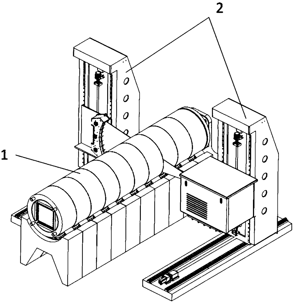
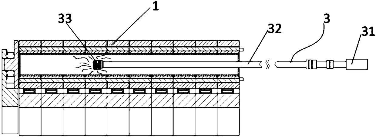
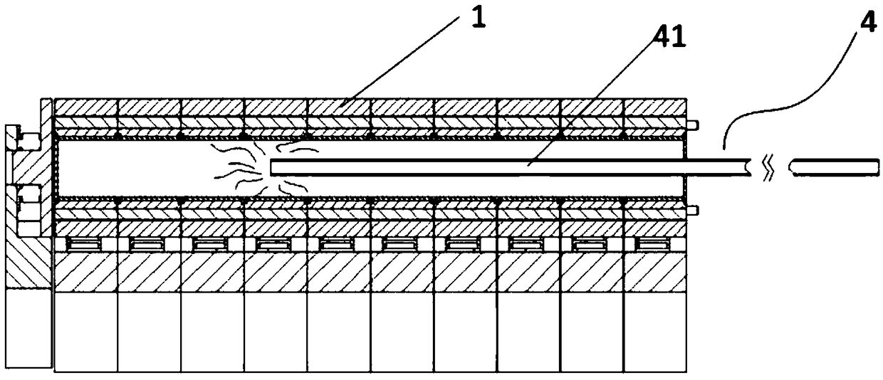
The invention belongs to the field of rock mechanical test equipment, and particularly relates to high-energy CT ultra-deep layer well drilling and fracturing integrated engineering test equipment. The high-energy CT ultra-deep layer well drilling and fracturing integrated engineering test equipment comprises a rotary experiment cabin used for containing rock samples, an electronic accelerator CTsystem, a well drilling system and a fracturing system. According to the high-energy CT ultra-deep layer well drilling and fracturing integrated engineering test equipment, through the well drilling system and the fracturing system, well drilling and fracturing simulation experiments are conducted on the rock samples, meanwhile, the state of the rock samples is monitored in real time by combiningwith the electronic accelerator CT system, and thus the rock state in the well drilling and fracturing processes can be learned in detail; and the fracturing simulation experiment effectively utilizesdrill holes formed along with the well drilling simulation experiment, thus well drilling and fracturing are integrated, further, through arrangement of a pressurizing device and a heating device, the almost real stratum temperature and pressure conditions in the well drilling and fracturing processes are further built, and through a multistage structure combination, adaptation of the whole equipment to the various rock samples is improved.

Description

technical field [0001] The invention belongs to the field of rock mechanics test equipment, and specifically provides a high-energy CT ultra-deep drilling and fracturing integrated engineering test equipment. Background technique [0002] Ultra-deep energy development (depth greater than 10,000m) is an inevitable choice to ensure national energy security, optimize energy structure and ecological environment protection in the future, and it is also a breakthrough for my country to seize the highland of future energy technology revolution. At present, the development of ultra-deep energy is faced with the difficult problems of complex geological conditions, harsh environment and great risks in oil and gas exploitation projects. [0003] Traditional drilling and fracturing simulations usually use experimental methods of physical simulation and numerical simulation under triaxial stress conditions. The above experimental methods have irreparable defects, such as the inability to...

Claims


Application Information

Patent Timeline
Patent Type & Authority Applications(China)
IPC IPC(8): E21B43/26E21B47/00
CPCE21B43/26E21B47/00
Inventor 李晓李守定郑博毛天桥
Owner INST OF GEOLOGY & GEOPHYSICS CHINESE ACAD OF SCI
Learn More