
Method for detecting and correcting error in optical mirror machining caused by airflow

An optical mirror surface and error detection technology, which is applied in the direction of using optical devices, measuring devices, instruments, etc., can solve the problems of low processing precision of optical mirror surfaces, and achieve the effects of improving reliability, improving ability, and improving processing accuracy

Active Publication Date: 2019-02-15
SHANDONG ZHONGHENG OPTOELECTRONIC TECH CO LTD
View PDF5 Cites 0 Cited by
  • Summary
  • Abstract
  • Description
  • Claims
  • Application Information

AI Technical Summary

Problems solved by technology

[0003] The purpose of the present invention is to provide a method for correcting optical mirror processing detection errors caused by airflow, so as to improve the accuracy of optical mirror processing detection error correction, and to overcome the optical mirror processing accuracy caused by the error accumulation that is easy to occur in the existing optical mirror processing process low defect

Method used


Image

  • Method for detecting and correcting error in optical mirror machining caused by airflow
  • Method for detecting and correcting error in optical mirror machining caused by airflow

Examples


Embodiment Construction

[0020] The present invention will be further described below with reference to the accompanying drawings.

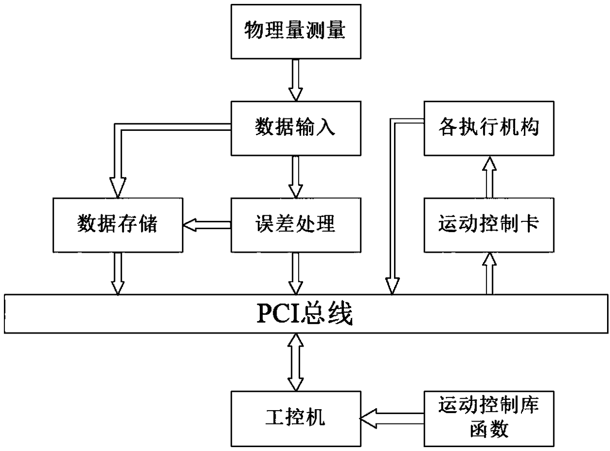
[0021] figure 1 Shown is a block diagram of the overall structure of an optical mirror processing detection error correction system caused by airflow, and its working process is as follows:

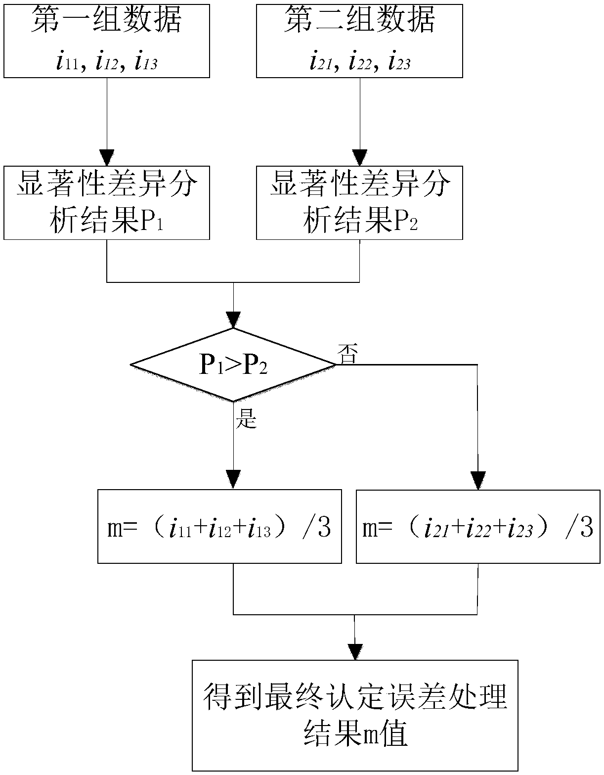
[0022] 1) The original optical mirror processing control system executes the processing process according to the set processing steps. After the processing of each step is completed, the optical mirror processing robot will suspend the processing action within a certain period of time. Physical quantity measurement, using an interferometer to measure the size of the current optical mirror, continuously measuring the readings 6 times, and dividing the measured values ​​into two groups, namely i 11 , i 12 , i 13 , i 21 , i 22 , i 23 , while measuring the size of the optical mirror, use the airflow detection device to measure the airflow value on the surface of the optical mirror...


PUM


Abstract

The invention discloses a method for detecting and correcting the error in optical mirror machining caused by airflow, and belongs to the field of optical machining. The method comprises the steps of:measuring the machining size of the optical mirror and the airflow value of the surface of the optical mirror; inputting the measured machining size and the airflow value into an error processing system, and obtaining an error processing result through an error processing program; transmitting the error processing result to an optical mirror machining control system through a bus; and the opticalmirror machining control system planning and correcting a motion track through a motion control function, and sending corrected data to an optical mirror machining execution mechanism, so as to control the optical mirror machining execution mechanism to complete the mirror machining correction action. According to the method for detecting and correcting the error in the optical mirror machining caused by airflow, the problem that inaccuracy of the optical mirror detection result caused by airflow change is solved; the reliability of the measurement result is improved; in combination with thefeedback control of the optical mirror machining execution mechanism, the machining process can be automatically adjusted; and the machining precision of the optical mirror is improved.

Description

technical field [0001] The invention relates to an optical mirror processing detection technology, in particular to a method for correcting an optical mirror processing detection error caused by airflow. Background technique [0002] Optical components have important applications in astronomical observation systems, laser nuclear fusion devices, precision optical measuring instruments, and other defense and civilian fields. Today's optical manufacturing capabilities still cannot fully meet the requirements of optical components in product processing accuracy and surface / subsurface quality . The surface quality of optical components is a key factor in determining the performance of the optical system. Poor surface quality will reduce the resolution and its scattering will cause a large energy loss. The performance index of the camera is greatly reduced, and in severe cases, it cannot be imaged at all. The reliability of detection technology is an important factor to ensure ...

Claims


Application Information

Patent Timeline
Patent Type & Authority Applications(China)
IPC IPC(8): G01B11/00
CPCG01B11/00
Inventor 程刚黄玉福徐庭钰顾伟郭锋张来宾
Owner SHANDONG ZHONGHENG OPTOELECTRONIC TECH CO LTD
Learn More