Water tunnel test device capable of generating oscillating freestream

An experimental device and water tunnel technology, applied in the fields of water conservancy and hydropower engineering, ship and underwater vehicle engineering, can solve problems such as the inability to simulate the influence of supercavitation flow of underwater vehicles, and achieve simple structure, precise control, and flexibility. control effect

Active Publication Date: 2019-02-15
NANJING UNIV OF SCI & TECH
View PDF9 Cites 5 Cited by
  • Summary
  • Abstract
  • Description
  • Claims
  • Application Information

AI Technical Summary

Problems solved by technology

[0004] The purpose of the present invention is to provide a water tunnel experimental device that can generate oscillating incoming flow, which is used to ...

Method used


Image

  • Water tunnel test device capable of generating oscillating freestream
  • Water tunnel test device capable of generating oscillating freestream
  • Water tunnel test device capable of generating oscillating freestream

Examples


Embodiment Construction

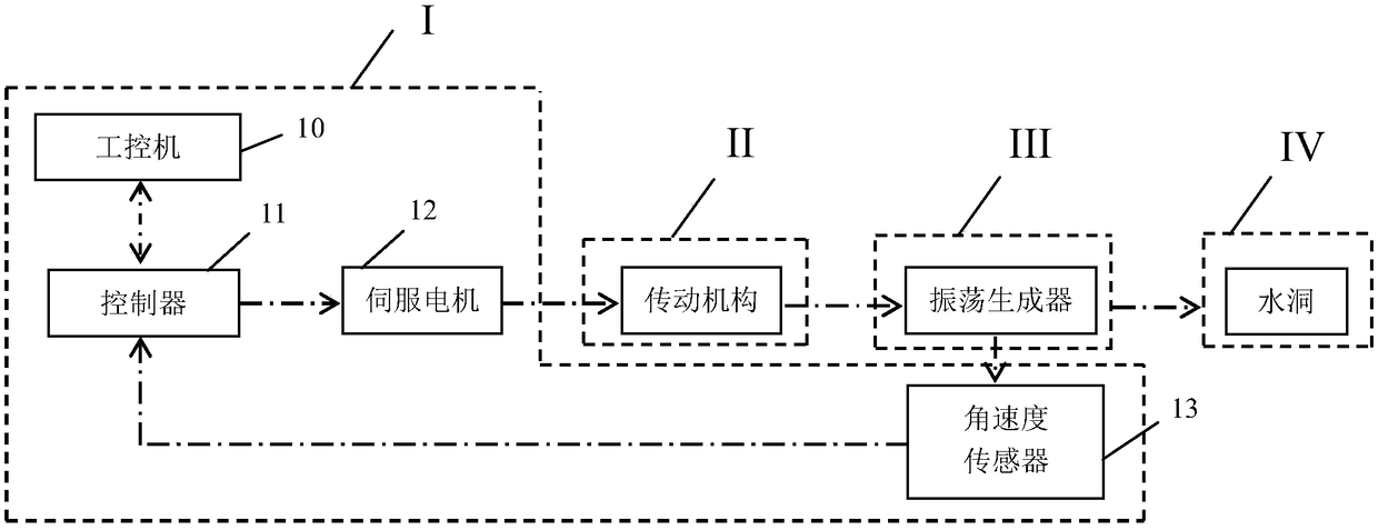
[0013] The water tunnel experimental device capable of generating oscillating incoming flow in the present invention is composed of four parts: a control system I, a transmission mechanism II, an oscillation generator III and a water tunnel test platform IV.

[0014] The control system includes an industrial computer, a controller, a servo motor and an angular velocity sensor.

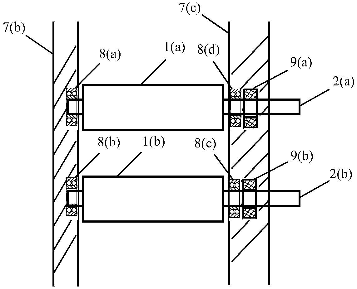
[0015] The transmission mechanism includes a connecting rod, a rotary pair, a flywheel, a bearing and a dynamic seal.

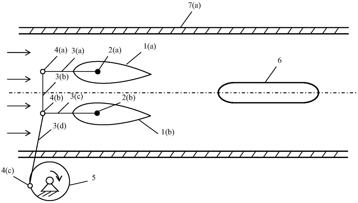
[0016] The oscillation generator includes a hydrofoil and a hydrofoil connection shaft.

[0017] The test platform includes a circulating water tunnel and an underwater vehicle model.

[0018] Working process: First, start the industrial computer, then adjust the flow parameters of the water tunnel to generate natural supercavitation flow around the underwater vehicle or ventilated supercavitation flow; next, start the servo motor through the controller to drive the servo motor When...


PUM


Abstract

The invention discloses a water tunnel test device capable of generating oscillating freestream. The water tunnel test device is composed of a control system I, a transmission mechanism II, an oscillation generator III and a water tunnel test platform IV. The control system comprises an industrial control computer, a controller, a servo motor and an angular speed sensor. The transmission mechanismcomprises a connecting rod, a rotating pair, a flywheel, a bearing and a moveable seal. The oscillation generator comprises a hydrofoil and a hydrofoil connecting shaft. The test platform comprises acirculating water tunnel and an underwater vehicle model. The test device is simple in structure and suitable for the cavitation flow test of various test models.

Description

technical field [0001] The invention belongs to the technical fields of ship and underwater vehicle engineering and water conservancy and hydropower engineering, and in particular relates to a water tunnel test device capable of generating oscillating incoming flow. Background technique [0002] In high-speed water flow, when the pressure at a certain location drops below the saturated vapor pressure, natural cavitation will occur. As the cavitation number decreases, natural cavitation can develop into a supercavitating flow. Taking the underwater vehicle as an example, at this time, the natural supercavitation formed by supercavitation will almost completely cover the underwater vehicle. In addition, in the case of low flow velocity, ventilated supercavitation can also be formed around the underwater vehicle by actively injecting air and other non-condensable gases on the head surface of the underwater vehicle. Whether it is natural supercavitation or ventilated supercavi...

Claims


Application Information

Patent Timeline
IPC IPC(8): G01M10/00
CPCG01M10/00
Inventor 胡常莉陈广豪陈少松王学德
Owner NANJING UNIV OF SCI & TECH
Why Eureka
Try Eureka