Water sample treatment system

A technology for processing systems and water samples, applied in the field of water treatment, can solve problems such as low degree of automation of organic matter detection devices in water, inability to process systems, etc., and achieve the effects of ensuring extraction efficiency and experimental accuracy, solving water inflow, and high degree of automation

Inactive Publication Date: 2019-02-15
LIHE TECH (HUNAN) CO LTD
View PDF8 Cites 0 Cited by
  • Summary
  • Abstract
  • Description
  • Claims
  • Application Information

AI Technical Summary

Problems solved by technology

[0006] The purpose of the present invention is to provide a water sample processing system, which solves the problem that the existing technology cannot integrate the extraction and analysis functions into one water organic matter processing system, and greatly improves the problem of low automation of the water organic matter detection device

Method used


Image

  • Water sample treatment system
  • Water sample treatment system
  • Water sample treatment system

Examples


Embodiment 1

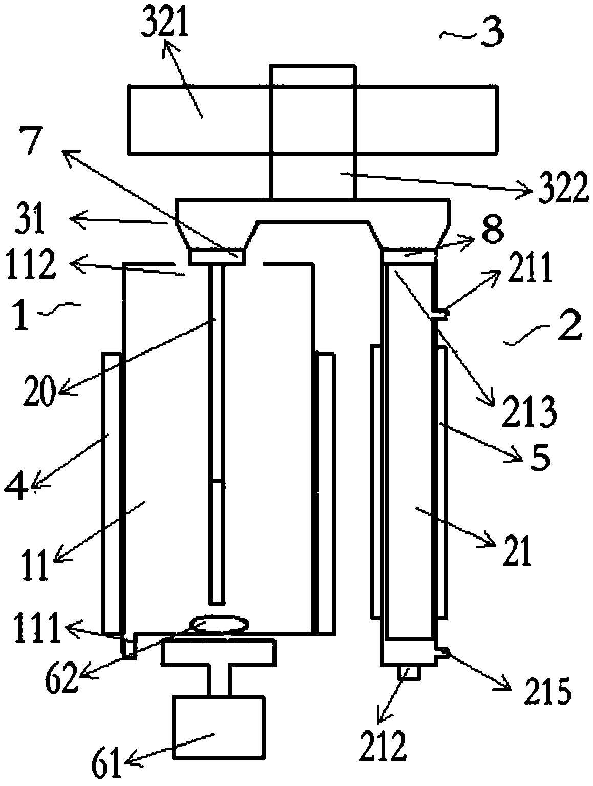
[0039] Such as figure 1 As shown, the tops of the extraction mechanism 1 and the analysis mechanism 2 in this embodiment are at the same level, and the linkage mechanism 3 is located at the top of the extraction mechanism 1 and the analysis mechanism 2 . The transportation part of the linkage mechanism 3 in this embodiment can move horizontally between the first chamber 11 and the second chamber 21, and drive the extract 20 held by the installation part 31 into the first chamber 11 for extraction, and then into the The second chamber 21 performs analysis. Specifically, the water sample inlet and outlet 111 in this embodiment is arranged at the bottom of the first chamber 11, the first extract inlet and outlet 112 is arranged at the top; the carrier gas inlet 211 is arranged on the side of the second chamber 21, and the carrier gas outlet 212 is arranged At the bottom, a second extract port 213 is located at the top. The first extract port 112 is level with the second extract...

Embodiment 2

[0048] This embodiment is basically the same as Embodiment 1. For the sake of brevity, in the description process of this embodiment, the same technical features as Embodiment 1 will not be described, and only the differences between this embodiment and Embodiment 1 will be described:

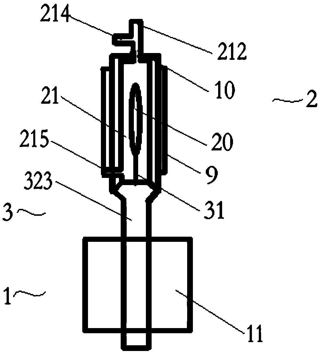
[0049] The extraction mechanism 1 and the analysis mechanism 2 in Embodiment 1 are arranged horizontally, and the extraction mechanism 1 and the analysis mechanism 2 in this embodiment are arranged vertically.

[0050] The analysis mechanism 2 in this embodiment is located above the extraction mechanism 1 and is connected through a linkage mechanism 3 . In this embodiment, the first extract inlet and outlet 112 is located at the top of the first chamber 11, the second extract inlet and outlet 213 is located at the bottom of the second chamber 21, the transport parts can move up and down, and the extract 20 is located between the extraction mechanism 1 and the analysis mechanism. 2 movement betw...


PUM


Abstract

The invention relates to the technical field of water treatment, and provides a water sample treatment system. The water sample treatment system comprises an extraction mechanism, an analytical mechanism, and a linkage mechanism. The extraction mechanism comprises a first chamber which is provided with a water sample inlet and outlet, and a first extract inlet and outlet. The analysis mechanism comprises a second chamber which is provided with a carrier gas inlet, a carrier gas outlet, and a second extract inlet and outlet, wherein the carrier gas outlet is connected to a chromatograph column.The linkage mechanism is provided with a mounting component and a transport component. The mounting component is fixed to the transport component and used for fixing the extract. The transport component can move between the first extract inlet and outlet and the second extract inlet and outlet. The water sample treatment system connects the extraction mechanism with the analytical mechanism through the linkage mechanism, integrates the extraction and analysis functions, and has high automation degree. The water sample treatment system can also extract and separate organic matter, can effectively isolate the water, and solve the problem of water inflow of the chromatograph column. The extraction mechanism simulates laboratory extraction methods to ensure extraction efficiency and experimental accuracy.

Description

technical field [0001] The invention relates to the technical field of water treatment, in particular to a water sample treatment system. Background technique [0002] Solid-phase microextraction technology uses fused silica fiber (extraction head) coated with a stationary phase to adsorb and enrich the analyte in the sample. Immerse the extraction head in the sample solution for a period of time, and stir the solution at the same time to accelerate the equilibrium between the two phases. After the equilibrium, take out the fiber head and insert it into the gas chromatography vaporization chamber to thermally desorb the adsorbed substances on the coating. After the extract is desorbed in the vaporization chamber, it is introduced into the chromatographic column by the mobile phase to complete the whole process of extraction, separation and concentration. [0003] In the field of environmental monitoring, quantitative analysis of organic pollutants in water is required, so s...

Claims


Application Information

Patent Timeline
IPC IPC(8): G01N30/06
CPCG01N30/06G01N2030/062
Inventor 文飘邹雄伟蔡志熊春洪
Owner LIHE TECH (HUNAN) CO LTD
Why Eureka
Try Eureka