Testing device for terminal antennas

A technology for testing devices and terminal antennas, applied in the direction of antenna radiation patterns, etc., can solve problems such as time-consuming, cumbersome process, and reduced test accuracy, and achieve the effects of reduced test time, high test accuracy, and simple operation

Active Publication Date: 2019-02-15
BEIJING XIAOMI MOBILE SOFTWARE CO LTD
View PDF16 Cites 8 Cited by
  • Summary
  • Abstract
  • Description
  • Claims
  • Application Information

AI Technical Summary

Problems solved by technology

[0005] The present disclosure provides a testing device for a terminal antenna, which can solve the problem in the related art that when determining the optimal position, the gold machine needs to be repeatedly debugged, and the process is cumbersome and time-consuming; in addition, in the working environment of the testing instrument After the change, the optimal position will change accordingly. If the antenna performance test is continued based on the line loss and space loss at the initially determined optimal position, the test accuracy will be greatly reduced.

Method used


Image

  • Testing device for terminal antennas
  • Testing device for terminal antennas
  • Testing device for terminal antennas

Examples


Embodiment Construction

[0035] The exemplary embodiments will be described in detail here, and examples thereof are shown in the accompanying drawings. When the following description refers to the accompanying drawings, unless otherwise indicated, the same numbers in different drawings represent the same or similar elements. The implementation manners described in the following exemplary embodiments do not represent all implementation manners consistent with the present disclosure. Rather, they are merely examples of devices and methods consistent with some aspects of the present disclosure as detailed in the appended claims.

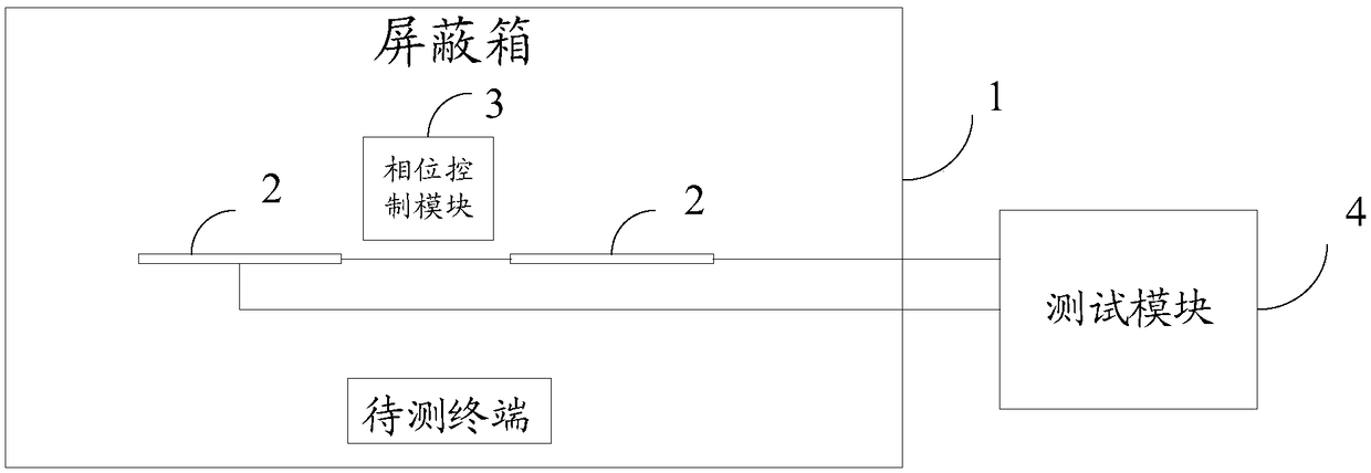
[0036] figure 2 It is a schematic structural diagram showing a testing device for a terminal antenna according to an exemplary embodiment. Such as figure 2 As shown, the testing device includes: a shielding box 1, at least two antennas 2, at least one phase control module 3, and a testing module 4. Wherein, the operating frequency bands between any two of the at least two ant...


PUM


Abstract

The invention discloses a testing device for terminal antennas, and belongs to the technical field of antennas. The testing device comprises a shielding box, at least two antennas, at least one phasecontrol module, and a testing module. The working frequency bands between any two of at least two antennas partially overlapped. At least two antennas and at least one phase control module are locatedin the shielding box. The testing module is located outside the shielding box and connected to at least two antennas. A phase control module is provided between any two antennas. Any two antennas areused to respectively receive a first signal transmitted by the terminal to be tested located at any position within the shielding box. The phase control module is used to respectively receive the first signal sent by any two antennas, and performs an antenna beam combining operation to obtain the position information of the terminal to be tested and a second signal. The testing module is used toperform antenna performance testing on the terminal to be tested in an overlapped working frequency band. The testing process of the embodiment of the invention is simple and convenient, and the testing accuracy is high.

Description

Technical field [0001] The present disclosure relates to the field of antenna technology, and in particular to a testing device for terminal antennas. Background technique [0002] With the rapid development of society and the improvement of living standards, users nowadays have higher and higher requirements for the performance of the terminal. However, the performance of the terminal antenna will directly affect the performance of the terminal. Therefore, testing equipment is usually used to test the terminal. The performance of the antenna in different frequency bands is tested by coupling. [0003] Related technologies are often used such as figure 1 The test device shown performs a coupling test on a terminal antenna, and the test device includes a shielding box, an antenna working in multiple frequency bands, and a tester. Among them, before using the device to test the antenna performance of the terminal under test, an additional device (called a gold machine) needs to be p...

Claims


Application Information

Patent Timeline
Patent Type & Authority Applications(China)
IPC IPC(8): G01R29/10
CPCG01R29/10
Inventor 刘达崔旭旺
Owner BEIJING XIAOMI MOBILE SOFTWARE CO LTD
Why Eureka
Try Eureka