Event-driven synchronous fault detection and control method for unmanned surface vehicles
An event-driven, fault detection technology, applied in the direction of test/monitoring control system, program control, general control system, etc., can solve the problems of high cost, large network communication bandwidth occupancy rate of SFDC module, large energy consumption of data transmission, etc.
- Summary
- Abstract
- Description
- Claims
- Application Information
AI Technical Summary
Problems solved by technology
Method used
Image
Examples
specific Embodiment approach 1
[0036] Specific implementation mode one: the specific process of this implementation mode is: inventing a synchronous fault detection and control method based on an event-driven surface unmanned vehicle, specifically according to the following steps:
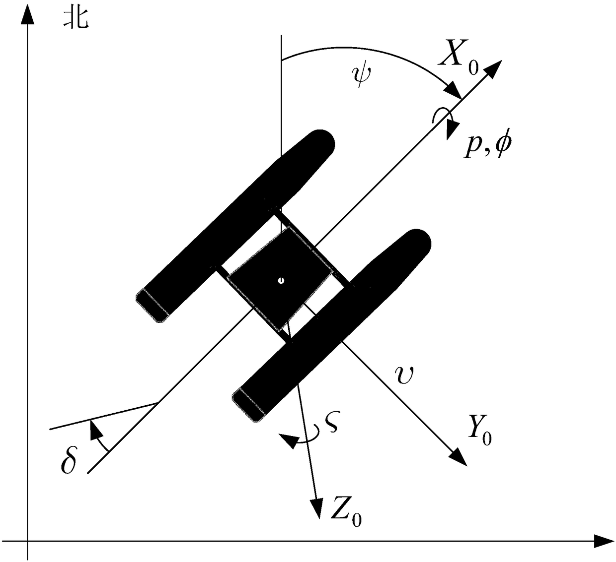
[0037] Step 1. The motion coordinate system of the surface unmanned vehicle is as follows: figure 1 As shown, here we only consider the traversing, swinging and rolling motions of the surface unmanned vehicle.
[0038] Establish the state space equation of the surface unmanned vehicle system according to the kinematic equation;
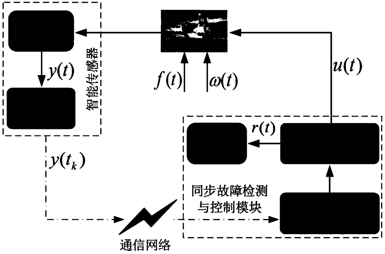
[0039] Step 2. Based on the state space model of the surface unmanned vehicle system established in step 1, design an SFDC module based on integral event-driven, and establish an augmented residual system under event-driven conditions;
[0040] Step 3. According to the performance index requirements of the surface unmanned vehicle, design the gain matrix based on the integral event-driven SFDC module,...
specific Embodiment approach 2
[0045] Specific embodiment 2: The difference between this embodiment and specific embodiment 1 is that the motion coordinate system of the surface unmanned boat in the step 1 is as follows: figure 1 As shown, here we only consider the traversing, swinging and rolling motions of the surface unmanned vehicle.
[0046] According to the kinematic equation, the state space equation of the surface unmanned vehicle system is established, and the expression is:
[0047]
[0048] In the formula, is the state of the USV system,
[0049] Where v(t) is the traversing velocity produced by the rudder of the surface unmanned vehicle, is the swing velocity of the surface unmanned vehicle, ψ(t) is the course angle of the surface unmanned vessel, p(t) is the roll velocity of the surface unmanned vessel, φ(t) is the roll angle of the surface unmanned vessel ; is the derivative of the USV system state;
[0050] w(t)=[w ψ (t),w φ (t)] T External disturbance for the surface unmanned ve...
specific Embodiment approach 3
[0061] Specific embodiment three: the difference between this embodiment and specific embodiment one or two is that the surface unmanned vehicle system matrix A, B, E 1 The expression is as follows:
[0062]
[0063] Among them, K vr , K vp , K dv , K dr , K dp For a given gain, T v , T r For a given time constant, ζ and w n are the damping coefficient and the undamped natural frequency, respectively.
[0064] Other steps and parameters are the same as those in Embodiment 1 or Embodiment 2.
PUM
 Abstract
Description
Claims
Application Information
 - R&D
- Intellectual Property
- Life Sciences
- Materials
- Tech Scout
- Unparalleled Data Quality
- Higher Quality Content
- 60% Fewer Hallucinations
Browse by: Latest US Patents, China's latest patents, Technical Efficacy Thesaurus, Application Domain, Technology Topic, Popular Technical Reports.
© 2025 PatSnap. All rights reserved.Legal|Privacy policy|Modern Slavery Act Transparency Statement|Sitemap|About US| Contact US: help@patsnap.com


