Unmanned aerial vehicle autonomous landing method, device and unmanned aerial vehicle

A drone and area technology, applied in the field of drones, can solve problems such as insufficient detection, inability to detect dangerous areas, drone landing and crashing, etc., to achieve the effect of improving accuracy and reducing the risk of crashes

Active Publication Date: 2019-02-15
SHENZHEN AUTEL INTELLIGENT AVIATION TECH CO LTD
View PDF12 Cites 9 Cited by
  • Summary
  • Abstract
  • Description
  • Claims
  • Application Information

AI Technical Summary

Problems solved by technology

[0003] However, the inventor found in the process of realizing the present invention that: at present, the autonomous landing protection technology equipped in the UAV only analyzes the overall situation of the area to be landed, and can only detect the overall smoothness of the area to be landed, but cannot detect The roof, cliffs, deep trenches and other dangerous areas that are flat but have obvious edge gaps, the detection is not comprehensive enough, so that there is still a risk of crashing when the drone lands

Method used


Image

  • Unmanned aerial vehicle autonomous landing method, device and unmanned aerial vehicle
  • Unmanned aerial vehicle autonomous landing method, device and unmanned aerial vehicle
  • Unmanned aerial vehicle autonomous landing method, device and unmanned aerial vehicle

Examples


Embodiment 1

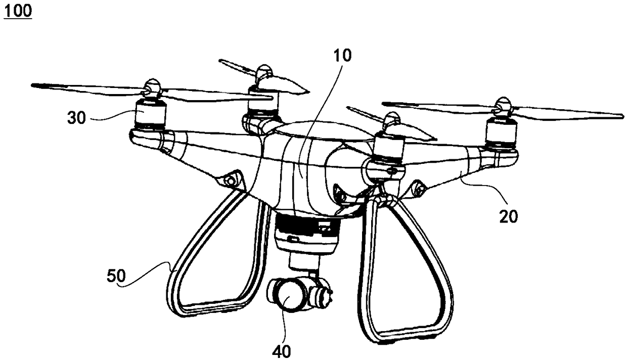
[0078] see figure 1 , is an unmanned aerial vehicle 100 provided by one embodiment of the present invention, including a casing 10, an arm 20, a power unit 30, a depth sensor 40, a landing gear 50, and a flight control system (not shown). The aircraft arm 20 , the depth sensor 40 and the landing gear 50 are all connected to the housing 10 , the flight control system is disposed in the housing 10 , and the power unit 30 is disposed on the aircraft arm 20 . Among them, the power unit 30, the depth sensor 40 and the landing gear 50 are all connected to the flight control system in communication, so that the flight control system can control the flight of the UAV 100 through the power unit 30, and can obtain the status of the UAV 100 through the depth sensor 40. The point cloud distribution map of the landing area can also control the contact between the landing gear 50 and the ground.

[0079] Preferably, the number of machine arms 20 is four, which are evenly distributed around...

Embodiment 2

[0129] see Image 6 , is a schematic flow chart of a method for autonomous landing of a drone provided by one embodiment of the present invention, which is applied to a drone, and the drone is the drone 100 described in the above embodiment, and the embodiment of the present invention The provided method is executed by the above-mentioned flight control system, and is used to realize partial detection of the UAV, improve the accuracy of detection, and reduce the risk of the UAV autonomously landing and crashing. The UAV autonomous landing method includes:

[0130] S100: Obtain a point cloud distribution map of the area to be landed.

[0131] The above-mentioned "area to be landed" is an area determined according to the existing UAV landing protection method with a flat surface and suitable for UAV landing. The area to be landed does not include water surfaces, bushes, slopes, etc., including flat ground, platforms , roofs, cliffs, etc.

[0132] The above "point cloud distrib...

Embodiment 3

[0176] The term "module" used below is a combination of software and / or hardware that can realize a predetermined function. Although the devices described in the following embodiments can be implemented in software, implementation in hardware, or a combination of software and hardware is also conceivable.

[0177] see Figure 7 , is a drone autonomous landing device provided by one of the embodiments of the present invention, the device is applied to a drone, the drone is the drone 100 described in the above embodiment, and the embodiment of the present invention provides The function of each module of the device is performed by the above-mentioned flight control system, which is used to realize the local detection of the drone, improve the accuracy of the detection, and reduce the risk of the drone's autonomous landing and crash. The drone's autonomous landing device includes:

[0178] Acquisition module 200, the acquisition module 200 is used to obtain the point cloud distr...


PUM


Abstract

The embodiments of the present invention belong to the technical field of unmanned aerial vehicle control, and relates to an unmanned aerial vehicle autonomous landing method, an unmanned aerial vehicle autonomous landing device and an unmanned aerial vehicle. The unmanned aerial vehicle autonomous landing method includes the following steps that: the point cloud distribution map of an area wherean unmanned aerial vehicle to land is acquired; a detection area in the point cloud distribution map is determined according to the actual landing area of the unmanned aerial vehicle in the point cloud distribution map, wherein the detection area refers to an area in the point cloud distribution map used for detecting the number of point clouds; the detection area is divided into at least two designated regions, each of the at least two designated regions is respectively corresponding to a portion of the area where the unmanned aerial vehicle to land; whether the number of point clouds in eachof the at least two designated regions is less than a preset threshold is judged; if the number of point clouds in a certain region in the at least two designated regions is less than the preset threshold, and the unmanned aerial vehicle is controlled to fly away from the designated region of which the point cloud quantity is less than the preset threshold, or the unmanned aerial vehicle is controlled to stopping landing. With the above method adopted, the local detection of the unmanned aerial vehicle can be realized, the accuracy of detection can be improved, and the risk of the crash of the unmanned aerial vehicle can be reduced.

Description

technical field [0001] Embodiments of the present invention relate to the technical field of UAV control, in particular to a method and device for autonomously landing a UAV, and the UAV. Background technique [0002] A drone is an unmanned aerial vehicle operated by a radio remote control device or its own program control device. With the development of UAV-related technologies and the complex changes in its application scenarios, more and more safety problems occur during the flight of UAVs. Therefore, UAVs are equipped with autonomous landing protection technology to prevent unmanned The plane crashed when it landed in an unknown environment. [0003] However, the inventor found in the process of realizing the present invention: at present, the autonomous landing protection technology equipped in the UAV only analyzes the overall situation of the area to be landed, and can only detect the overall smoothness of the area to be landed, but cannot detect The roofs, cliffs, ...

Claims


Application Information

Patent Timeline
Patent Type & Authority Applications(China)
IPC IPC(8): G05D1/10
CPCG05D1/101B64C39/024B64D45/04G05D1/102G01C21/3889G01C21/3896G01C21/20B64U2101/30B64U2201/10B64U70/00B64U10/13
Inventor 郑欣
Owner SHENZHEN AUTEL INTELLIGENT AVIATION TECH CO LTD
Why Eureka
Try Eureka